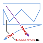
A feature lacking in Visio, like for-EVER, is the ability to align text along a connector’s path.
Now, Visio 2010’s new ShapeSheet functions and capabilities finally deliver.
Today we’ll show-off the cool new connector that I’ve developed for you, and get a very light technical explanation as to how it works!
In a previous post, I was re-creating (for fun!) a flowchart that I had seen in the Süddeutsche Zeitung.
In that flowchart, I needed to place connector-text along the actual line of the connector. Every time I adjusted the drawing, the angle of the connector changed, and I had to re-orient the text using the Text Block Tool.
You can see here how I am hastening the onset of arthritis with too much mousing:
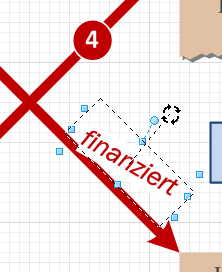
Getting connector text to do this automatically is something I’ve wanted to implement for a long, long time. But the ShapeSheet couldn’t do it. I always needed to resort to code to get it to happen.
Today, however, I fired up my Visio 2010 beta and put some new features to work. The result is a connector that places text at the very end, rotated to match the angle of the last part of the connector.
No matter how many segments the connector has, what the terminal angle is, or the line-style, the text ends up in a reasonable position, and correctly aligned with the end:
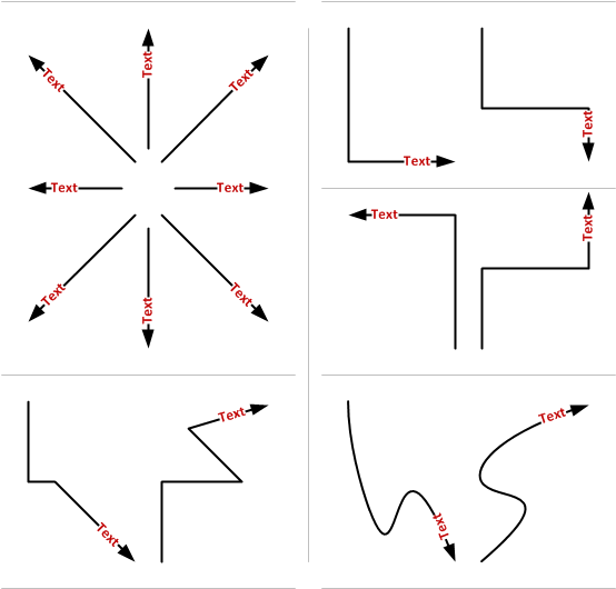
Not bad, eh?
New ShapeSheet Capabilities Make it Possible!
Visio has added two new functions that I’ve used in two custom User-defined cells of the connector’s ShapeSheet. Take a gander:
User.angPathEnd = ANGLEALONGPATH( Geometry1.Path, 1 )
User.pntPathEnd = POINTALONGPATH( Geometry1.Path, 1 )
Not only do we have new functions in Visi0 2010, but we are able to refer to new types of objects. Up until now, we had to refer to ShapeSheet cells, and only ShapeSheet cells. But you can see that “Geometry1.Path” refers to a thing–a geometry section that is a group of cells. That’s new, and it’s pretty useful.
As you use an automatic connector in Visio, extra segments get added or removed from the connector. This has made it impossible to refer to the “last point” and “next-to-last point”, because ShapeSheet cells were being created and destroyed as the connector was reconfigured.
Now I can simply ask the ShapeSheet to tell me the angle along the path of “Geometry1.Path”, at 100% along the path’s lenght (that’s the “1” you see in both functions)
Using similar syntax, I can ask for the end point too. The illustrated POINTALONGPATH function tells returns a Visio point-structure (combination of x- and y-values) for the point which is 100% of the way along Geometry1.Path.
This information was enough for me to relocated the shape’s text at the very end of the connector, offset and rotated correctly.
Bonus Features
Getting the text to be aligned at the end of the connector was fun. But I thought; “Hmm. That control handle that you can use to move text on Visio’s default connectors is also pretty cool!”
So I added a right-click context menu action to allow you to choose.
Notice the new, context Action menus that feature the fly-out, cascading items! You can read about these on John Goldsmith’s Custom Context Menus.
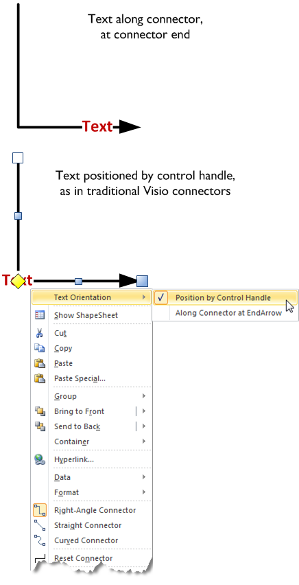
Here’s another look at the variations:
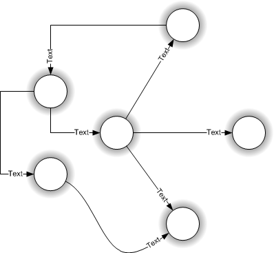
Have fun with this new connector. Note that this file uses new features available only in Visio 2010. while the file will likely open in Visio 2007 or Visio 2003, the shape won’t work as advertised.
If you don’t have Visio 2010, you might investigate getting a copy of the beta: Visio 2010 Beta: Sign Up Now!
Download “Text Along Connector 2010”
s!Aj0wJuswNyXlhwsa1wpYb1vX4lnt – Downloaded 14744 times – 103.00 B
Wow – one more reason I keep abusing Visio as a graphics program…
Doesn’t this functionality exist already in Visio 2007? I can position text on a connector by using the text block tool (click on the little down arrow on the text tool icon on the toolbar).
Don,
The angle of the text automatically matches that of the connector.
What you are referring to in previous versions of Visio was the ability to manually position the text somewhere along the connector. To do what I’ve created would require you to 1. move the text box and 2. rotated it to match the inclination of a portion of the connector.
The illustrations above look obvious and unimpressive because the behavior is natural and correct. But we really haven’t seen this possibility (without code) until now.
How do you get this connector to do the fancy zig-zag paths?
Hi DaveC,
Check out this article: Making Bends in Visio’s Dynamic Connector
Now if i could get this for text at both ends at the same time, that would be perfect.
Jeremy,
a cludgy but effective solution would be to create two connectors between your objects, one in each direction.
Of course two connectors would look pretty silly if they followed different routes between the objects, so only really useful for straight connectors.
This looks like it could solve a few problems for me. Many thanks.
Great, it is exactly what I was looking for !
But really, really why it isn’t built in Visio 2010 ??
Really wired.
Then Chris,
to be complete how easily you could add the sub-menus :
Along connector at Middle
Along connector at Beginning
Pierre,
I don’t understand your question. It IS built in Visio 2010, and could only be built in Visio 2010, because it uses new ShapeSheet functions.
Of course I could add the other functions, but so could you! 🙂 Thanks for the ideas.
Chris
Well, I must have missed something.
The fact is that I’m very disturbed by the Visio 2010 ribbon interface.
I found how to rotate the text manually along the connector but not how to have the text of the arrow follow automatically its direction !
Pierre
Hi Pierre,
It isn’t an easy thing to do. The point of this article is to show that it *can* be done. It requires using Visio’s ShapeSheet, something that takes a while to learn.
I have considered making a more advanced shape, but is probably something that I will have to create for sale because I don’t have a lot time these days for give-aways.
Thanks for visiting the site and asking questions, by the way!
Chris
I understand better now 😉
So the question is still open :
Why it isn’t built into Visio 2010 ?
Pierre
I think Visio has to tread a fine line between general-purpose and special-purpose. With Visio 2010 (Premium), they’ve added a lot of process-specific stuff. This will help a lot of people, but it could get in the way of non-process diagramming folks and third party solutions. The Visio universe is tricky because it is so huge.
I am using Visio 2003 SP3 and thought I would try it and it works perfectly.
Hi CEC,
You may be getting lucky, or just aren’t noticing what the feature is intended to do. This should definitely NOT work properly in Visio 2003!
Hello,
In the early versions (around 2000), one could add a text box around the text on the connector. Does anyone know how to do this in 2007? Is it even possible?
Hi Barbara,
Do you mean add an outline around the text box, or just a background fill? You can still add a background color to any text block via the Format > Text dialog. Go to the “Text Block” tab and look for the “Text background” setting.
Hi Visio Guy,
I can add the background color, but I’d really prefer an outline around the text. The alternative would be to move the text box closer to the connector and shape location which I just learned how to do. I have a diagram with many lines, and the text boxes tend to overlap.
Thanks for the tips on other questions. I just discovered this site this morning, and it seems to be a good source for help. Microsoft On-line is too general.
Hi,
I’m trying to adapt your shapesheet definition to Add “Along Connector at StartArrow” and “Centered Along Connector” … but i don’t undesrand how works Visio function…
there is no one who has already done this?
Thanks in advance…
Hi G,
It involves some ShapeSheet work. First, for the middle of the connector. First add this cell and formula:
User.pathFraction = IF(User.txtState=1,1,IF(User.txtState=2,0.5,0))
Now, modify two existing cells:
User.angPathEnd = ANGLEALONGPATH(Geometry1.Path, User.pathFraction)
User.pntPathEnd = POINTALONGPATH(Geometry1.Path, User.pathFraction)
These cells are now more general, and should actually be renamed User.angPath and User.pntPath, since they will soon for both the end and the midpoints.
Add a new Actions row, name it Actions.TextAtMid, then set these formulas:
Actions.TextAtMid.Menu = “At Connector Mid-point”
Actions.TextAtMid.Checked = User.txtState=2
Actions.TextAtMid.Action = SETF(GetRef(TxtPinX),”GUARD(User.TextPin)”)+
SETF(GetRef(TxtPinY),”GUARD(User.TextPin)”) +
SETF(GetRef(TxtAngle),”User.TextAngle”) +
SETF(GetRef(Controls.TextPosition.YCon),5) +
SETF(GetRef(User.txtState),2)
Actions.TextAtMid.FlyoutChild = True
Remember this only works for Visio 2010 as of this writing. Older versions don’t support these ShapeSheet functions.
Thanks a lot Mr. Visio Guy 🙂
Hu,
Is it possible to center text on middle of connector? :s
I know I’m exigent… but it’s so pleasant to have text on middle of connector… 🙂
And so, you’ll be able to update your attachment with differents examples :p
Hi,
I have the same question as guest before me. Is it possible to center text on middle of connector?
I try to fix it for 5 days, and without luck.
Is it possible, to have text box on both sides?
Thanks
BR Bozo
Hi Bozo,
If you’re talking about this connector–the download that accompanies this article–then yes.
As it says in the article, just right-click and choose “Text Orientation > Position by Control Handle”. You can then move the control handle to the center of the connector – just pull on the yellow diamond handle.
For regular Visio connectors, the control handle is always there.
In either case, you don’t need to use the Text or Text Block tools. The control handles save you the trouble!
How about a connector with text in the front, middle, and end.
I’ve been working on this for 2 days now. I can get the text angle correct, but I cannot seem to pin it to the line; though it’s relative to where I want it on the line.
This would be useful for connecting network devices. First text could be the port the cable is going out of, second text could be a MAC address or IP address, and third text would be the port or client the cable is plugged in to.
Thanks for the suggestion, Aaron. I’ve added an item to my Task list.
+1 for the connector with text at start, middle, end
I have found that the text inverts before the connector is a the vertical which means on a steeply decending arrow the text is upside down.
Thank you for a great post!
It has been extremely helpful to me in a recent project.
Glad to help, Marcus. Thanks for letting us know this worked well for you!
wow, this is great, but having the text in the middle would be great. How could that be done?
thanks a lot for that. Worked very well for me.
I am glad that u are out there. 😉
Hello
For those who need all three (“Middle”, “Beginning”, “Start”) I have tuned the Visguy’s script. Here is the code for all three:
User.angPathEnd=ANGLEALONGPATH(Geometry1.Path,User.pathFraction)
User.pntPathEnd=POINTALONGPATH(Geometry1.Path,User.pathFraction)
User.TextAngle=User.angPathEnd+GRAVITY(User.angPathEnd)
User.TextPin=PNT(PNTX(User.pntPathEnd)-TxtLocPinX*COS(User.angPathEnd),
      PNTY(User.pntPathEnd)-TxtLocPinX*SIN(User.angPathEnd))
User.txtState=2
User.pathFraction==((User.txtState-1)/2)+((1-((User.txtState-1)/2))*
      TxtWidth/PATHLENGTH(Geometry1.Path))
Action.Row_1.Action=""
Action.Row_1.Menu="Text Orientation"

Action.Row_2.Action=SETF(GetRef(TxtPinX),"SETATREF(Controls.TextPosition)")+
      SETF(GetRef(TxtPinY),"SETATREF(Controls.TextPosition.Y)")+
      SETF(GetRef(TxtAngle),0)+
      SETF(GetRef(Controls.TextPosition.YCon),0)+SETF(GetRef(User.txtState),0)
Action.Row_2.Menu="Position by Control Handle"
Action.Row_2.Checked=User.txtState=0

Action.Row_3.Action=SETF(GetRef(TxtPinX),"GUARD(User.TextPin)")+
      SETF(GetRef(TxtPinY),"GUARD(User.TextPin)")+
      SETF(GetRef(TxtAngle),"User.TextAngle")+
      SETF(GetRef(Controls.TextPosition.YCon),5)+SETF(GetRef(User.txtState),1)+
      SETF(GetRef(Para.HorzAlign),User.txtState-1)

Action.Row_3.Menu="Start"
Action.Row_3.Checked=User.txtState=1

Action.Row_4.Action=SETF(GetRef(TxtPinX),"GUARD(User.TextPin)")+
      SETF(GetRef(TxtPinY),"GUARD(User.TextPin)")+ _
      SETF(GetRef(TxtAngle),"User.TextAngle")+
      SETF(GetRef(Controls.TextPosition.YCon),5)+ _
      SETF(GetRef(User.txtState),2)+SETF(GetRef(Para.HorzAlign),User.txtState-1)

Action.Row_4.Menu="Mid"
Action.Row_4.Checked=User.txtState=2

Action.Row_5.Action=SETF(GetRef(TxtPinX),"GUARD(User.TextPin)")+
      SETF(GetRef(TxtPinY),"GUARD(User.TextPin)")+ _
      SETF(GetRef(TxtAngle),"User.TextAngle")+SETF(GetRef(Controls.TextPosition.YCon),5)+ _
      SETF(GetRef(User.txtState),3)+SETF(GetRef(Para.HorzAlign),User.txtState-1)

Action.Row_5.Menu="End"
Action.Row_5.Checked=User.txtState=3
For those who don’t want to type it all manually, Here you can take an example file (save it as .vdx and open in Visio 2010)
Ilya, Thanks for the post, it works great. I’m curious though if it would be possible to have text at more than one position? I’d like to be able to label the beginning and end points of the connector. In an ideal world, I could even add text to the middle as a description of the connection.
FYI, I would gladly pay for the capability to have labels at any combination of the beginning, end and middle of a connector. I’m sort of able to do it now with multiple connectors based on Ilya’s post but it’s not elegant.
To Joe
Hey, you are talking about labels at any combination but there is only one text label per connector. I doubt it’s possible to edit three labels independently.
If this is placed on a filled shape, the text block on the connector becomes white. I’m aware that you can (1) give the text block a background color such that the line breaks are retained, or (2) set background fill to none (or 100% transparency with any color) at which point the text block will take on the color of whatever is behind it, but in this case, the line breaks are not retained. Is there a way to replicate (1) automatically so you don’t have to match the line’s text box background color every time a line is placed on a different background?
Hi Dave,
If you’re using Themes and backgrounds (ala: Insert > Background), then you can give the text the “Background” fill color (third column in Fill drop-down). Then, if you change the theme, the background color will change for both the background and the text object.
If you’re looking for a “pickup the color that is beneath me” function, then I don’t know of any, save for custom code that could be written to do a decent job of it.
Hello Visio Guy,
I’m using your connector. It is awesome, thank you for it. I think that there might be a problem with it though. It is an issue that I think Sca1ey was referring to. When you select the “Position by Control Handle” the text does not invert at 90 degree but more closer to what I would think 60 degree would be.
Where would I look to fix that?
Hmm, not sure what you’re talking about. When the text is positioned by control handle, it is always level, so there is no inversion.
When positioned automatically, the text orients toward the right or bottom sides of the page (so you don’t have to turn your head completely around).
The flips happen like this: if the line is at an angle between -60deg and 120deg, the text stays at the same angle as the line. If the line is greater than 120deg and less then 300deg, then the text flips 180deg, which orients it towards the right or bottom sides of the page.
Two questions or guidance on where to look:
1. Is there a way to put the Connector Text into the Shape Properties so it appears on the report, and then use the shape sheet to display that text on the connector?
2. Unrelated – heavy users of this great tool since early 90s. have exhausted hundreds of hours trying to figure out how to get formatting into the shape data fields so the reports work. using 2010 now and I don’t know why there is an option to run a report in html, and html tags put into the shape data don’t convert. If an effetive link (I use doubleclick and mouseover extensibly) to a formatted narrative could be seamless, this would be a much more powerful tool for training and process documentation. It’s got a place for all the information, but it’s too much work. Even a line wrap in the data shape view would solve so many problems!!
Great article, and I’ll keep searching as the need wont’ go away until I do!
Hey Visio Guy, is there a way to put a box around the connector text to make it stand out more?
Lots of Thanks!
Victor.
There seems to be a problem with the “text-at-the-end” connector. Everything looks great when I first draw out the connectors. If I save and close the file and then reopen it, some of the text is now tilted at random angles. Not all of the connectors are like this, just a few.
Since I can’t post a screenshot here, I’ve created a dropbox link so you can see what I am talking about:
https://www.dropbox.com/sh/z0chfdcuof1l86j/AAAy6WZk7Awzs26pwpfs0clYa
Any idea why this is happening? How can I fix it so the text stays where I want it? I thought you might like to know so you can improve the code if it happens to be a coding issue. If it’s something that I’m doing wrong, please help educate this noob so I don’t keep making the same mistake!
Thanks,
-Brian
Using Visio 2013
How do I implement this on an existing Visio file? I don’t have much experience with visual basic.
Hi Joe,
Well, the behavior is actually controlled through the ShapeSheet, so Visual Basic isn’t needed. However, you might be using code to retro-fit existing on-page connectors with the behavior.
I can’t explain how to edit shapes with automation in a simple blog-comment thread, but here are a few hints:
You can add ShapeSheet sections programmatically, and access ShapeSheet cells via shp.CellsSRC or shp.Cells(“somecellname”), then you can set the results or the formulas for various cells:
Thank you sooooooooooo very much for this! I hope Visio is paying you royalties for this creation! It was a life save for my colleague.