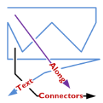
A feature lacking in Visio, like for-EVER, is the ability to align text along a connector’s path.
Now, Visio 2010’s new ShapeSheet functions and capabilities finally deliver.
Today we’ll show-off the cool new connector that I’ve developed for you, and get a very light technical explanation as to how it works!
In a previous post, I was re-creating (for fun!) a flowchart that I had seen in the Süddeutsche Zeitung.
In that flowchart, I needed to place connector-text along the actual line of the connector. Every time I adjusted the drawing, the angle of the connector changed, and I had to re-orient the text using the Text Block Tool.
You can see here how I am hastening the onset of arthritis with too much mousing:
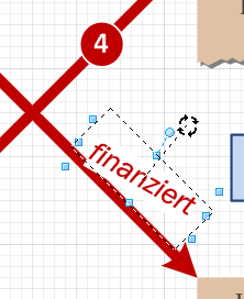
Getting connector text to do this automatically is something I’ve wanted to implement for a long, long time. But the ShapeSheet couldn’t do it. I always needed to resort to code to get it to happen.
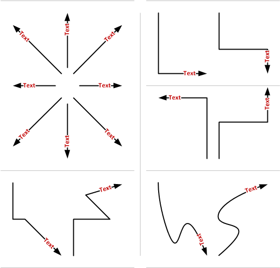
Today, however, I fired up my Visio 2010 beta and put some new features to work. The result is a connector that places text at the very end, rotated to match the angle of the last part of the connector.
No matter how many segments the connector has, what the terminal angle is, or the line-style, the text ends up in a reasonable position, and correctly aligned with the end:
Not bad, eh?
New ShapeSheet Capabilities Make it Possible!
Visio has added two new functions that I’ve used in two custom User-defined cells of the connector’s ShapeSheet. Take a gander:
User.angPathEnd = ANGLEALONGPATH( Geometry1.Path, 1 )
User.pntPathEnd = POINTALONGPATH( Geometry1.Path, 1 )
Not only do we have new functions in Visi0 2010, but we are able to refer to new types of objects. Up until now, we had to refer to ShapeSheet cells, and only ShapeSheet cells. But you can see that “Geometry1.Path” refers to a thing–a geometry section that is a group of cells. That’s new, and it’s pretty useful.
As you use an automatic connector in Visio, extra segments get added or removed from the connector. This has made it impossible to refer to the “last point” and “next-to-last point”, because ShapeSheet cells were being created and destroyed as the connector was reconfigured.
Now I can simply ask the ShapeSheet to tell me the angle along the path of “Geometry1.Path”, at 100% along the path’s lenght (that’s the “1” you see in both functions)
Using similar syntax, I can ask for the end point too. The illustrated POINTALONGPATH function tells returns a Visio point-structure (combination of x- and y-values) for the point which is 100% of the way along Geometry1.Path.
This information was enough for me to relocated the shape’s text at the very end of the connector, offset and rotated correctly.
Bonus Features
Getting the text to be aligned at the end of the connector was fun. But I thought; “Hmm. That control handle that you can use to move text on Visio’s default connectors is also pretty cool!”
So I added a right-click context menu action to allow you to choose.
Notice the new, context Action menus that feature the fly-out, cascading items! You can read about these on John Goldsmith’s Custom Context Menus.
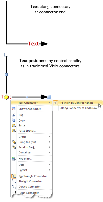
Here’s another look at the variations:
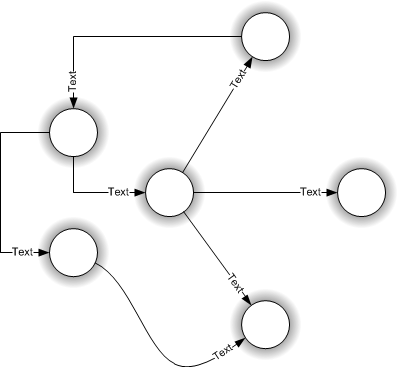
Have fun with this new connector. Note that this file uses new features available only in Visio 2010. while the file will likely open in Visio 2007 or Visio 2003, the shape won’t work as advertised.
If you don’t have Visio 2010, you might investigate getting a copy of the beta: Visio 2010 Beta: Sign Up Now!
Download “Text Along Connector 2010”
s!Aj0wJuswNyXlhwsa1wpYb1vX4lnt – Downloaded 14744 times – 103.00 B
hello
I have a question
you can change the color of a dynamic connector in c# I tried this code:
//set lable color
connector.Characters.set_CharProps(
(short)Microsoft.Office.Interop.Visio.
VisCellIndices.visCharacterColor,
(short)Utilities.GetVisioColor(Colors.Olive));
//set the shape back color
connector.get_CellsSRC((short)VisSectionIndices.visSectionObject,
(short)VisRowIndices.visRowFill, (short)VisCellIndices.visFillForegnd).FormulaU = “RGB(0,128,0)”;
but it does not work change the color but not dell’ettichetta connector
thanks anyway
Hi Visio Guy,
I’m experiencing the same issue that Brian92127 is above. I’m also using Visio 2013 (64-bit). The connectors work, but it seems that the text box location and orientation is not recalculated when the file is opened. Do you have any thoughts as to why that could be?
Thanks!
Hi Brian92127 and Joshua Colson,
I’m pretty sure I’ve seen the problems you’ve experienced, but I can’t recall in detail, and I don’t have time to investigate right now. Comment back in a few weeks to remind me to look at it again!
Hello again Visio Guy,
Thank you for responding. I’ve been digging and while I haven’t found the problem, I did find some additional information. It would seem there are others having the issue and one person found that saving the document in Visio 2010 format is a workaround to the problem. That is, assuming no 2013 features are required in the diagram.
See Dynamic Connector’s Text Randomly Moves
Hi Visio Guy,
Is there a way to center the text?
Bradford, this isn’t an elegant solution because of some of the embedded names in the custom fields that Visio Guy created, however…
Right-click the shape, and select “Show Shapesheet”, then look for the section called “User-defined Cells”, change the formula for User.angPathEnd from:
“=ANGLEALONGPATH(Geometry1.Path,1)”
to
“=ANGLEALONGPATH(Geometry1.Path,0.5)”
…and change User.pntPathEnd from:
“=POINTALONGPATH(Geometry1.Path,1)”
to
“=POINTALONGPATH(Geometry1.Path,0.5)”
Also note, unless you edit the ‘Text-at-end dynamic connector’ master shapesheet, the change will only affect your selected shape, and not all of them on the page.
Good luck!
—
Joshua Colson
Also, if it wasn’t obvious already, you can move the text to wherever you’d like along the path by adjusting that value. It is a percentage along the path, so 1 = 100% and 0.5 = 50%, and so on.
awesome, thanks for reply.
Hey Visio Guy,
I just wanted to give a quick update on the connector text placement issue. I investigated the problem and I found that the coordinate information was being saved properly into the Visio 2013 format file. All of the shapesheet data is correct in the saved file. However, when Visio loads the file is when things get funky. Given that, I figured it was probably a bug, or at least beyond my understanding of the application.
So, I opened a support case with Microsoft. That was about three weeks ago and they’ve finally determined that it is likely a bug in Visio. They’ve asked me to provide an impact statement so that they can prioritize creating a hotfix. I’ll be providing that to them soon. However, I wanted to make sure others knew the findings so they don’t spend too much time trying to solve the problem on their own.
I’ll provide an update when/if MS decides to create a hotfix for the problem.
Thanks.
—
Joshua Colson
Thanks for the help on this guys! I was able to use this to create the mid-oriented text as well! Great!
Is there any way to prevent the text from flipping (to be readable)?
when you move the end point left or right, the text flips so its readable… while making network diagrams, this would flip and be backwards. for example, i would type into the text box “G0/1 F0/22” , indicating interfaces for each side the device connects to. If I move one object to the left or right, the text flips and would indicate the wrong interfaces at the respective devices.
Kind of hard to explain, i hope you can follow!
Dear Visio Guy,
Thank you for this shape. These have greatly improved the conveyance of information in my busy diagrams.
This particular shape doesn’t copy and paste using the + DRAG functionality that I am used to. Is this intentional? What is overriding the + DRAG functions?
Thanks,
Nick (MXDSGNL)
Hi MXDSGNL,
It does drag-copy, actually, but it’s tricky because the shape has a hyperlink.
Solutions:
1. Edit the master and remove the 3 hyperlinks
2. Mouse down on the shape BEFORE you press Ctrl. Then press Ctrl and you can drag a copy. The hyperlink mouse-over icon messes it up if you press Ctrl too soon.
Dear Visio Guy,
Thanks for the quick response. I use these connectors very often. I think that one other beneficial configuration for the connector would be to set the text anchor a fixed distance from the end. The problem with POINTALONGPATH is that it uses percentage. So slight differences in connector length cause the text to move out of alignment.
–a———-[]—–b–[]
—a————[]—b-[]
–a———-[]—–b–[]
—a————[]—b-[]
This is simple for a horizontal connector, I added a shape data parameter to offset the “X” portion of the pnt along path, set the point along path to 1. Now, regardless of the length of the connector, the text will be aligned.
Not sure how to figure out the X and Y offset for a specified amount of fixed path length. Do you have any advice?
This is what would be nice
SHAPE DATA = .1″
-a———-[]——b-[]
-a————[]—-b-[]
-a———-[]——b-[]
-a————[]—-b-[]
Thanks!
Nick
Thank you! Thank you! Thank you! This feature makes my diagram so much more readable.
Thank you ! this is really great ! would it be possible to have the same with 2 label ? one label at the beginning and one label at the end of the form with exaclty the same behaviour.
This would be the most useful form I’ll ever use !
Thanks
I am working with a VISIO file that has over 100 objects that are all lined with many of them having many linking points. That being said, there are connections lines all over the place cross crossing each other which makes them hard to follow. Is there a way to select an object and have it jump me to the object it is connected to (forward arrow) as opposed to having to manually move around the sheet to find the connection?
Thank you,
LUD
Hi LUD,
Visio doesn’t have a built-in function for jumping to connector ends (but it needs one).
I have prototyped add-in code that does this, but never polished anything completely for a nice download or product.
A few ideas on how an add-in or VBA macro might work:
– Create hyperlinks in the connector that reference the “from” and “to” shape. However, this would need to be updated every time a connector was reconnected.
– Find the location of the end point and zoom/pan/center the active window to that point.
I tried editing to allow two text boxes. One at the beginning and one at the end. But with my limited Visio experience, it doesn’t look like it’s possible. Any advice on how to do that?
BTW, this feature wasn’t lacking “forever”; it was only lacking since Microsoft “improved” the version they acquired way back when. Visio 5, which was prior to Microsoft’s acquisition, supported this feature quite automatically, with options for changing it. All of that said, I’m really glad I found this post because I’ve been trying to figure this out ever since!
How do I do this in Visio 2019?
The methodology should be the same. The shape handles probably look different after all these years.
Hello Visio Guy,
As always I am super late to this party and it’s probably over. LOL.
I was needing the text of multiple connectors to be their ID()s so that I can very quickly assign them colors, to show current. Problem is that every time I move a shape I would have to go back and realign all the numbers. GRRRRR!.
Well thanx to you and this other guy, who has a connector with two text boxes and disappearing connector line leaving just the text box ends, I was able to create my own.
However Your equations, sin, cos, and others were just not my strong suit. So I rendered it down to mathematics that I can understand. Calculations and 10 is in millimeters.
Prop.Distance = 10
User.PathLengthDiv = 1/FORMAT(0 mm+PATHLENGTH(Geometry1.Path),”0.0000″)
Beginning(0), Mid-connector(0.5) or End (1)
User.BMorE = 0
User.CalcDistance = IF(User.BMorE=0.5,0.5,IF(User.BMorE=0,””,”1-“)&User.PathLengthDiv*Prop.Distance)
User.pntPath = POINTALONGPATH(Geometry1.Path,User.CalcDistance)
User.angPath = ANGLEALONGPATH(Geometry1.Path,User.CalcDistance)
User.TextPin = PNT(PNTX(User.pntPath),PNTY(User.pntPath))
And that is basically it. I kept the Actions section the same with your SETF’s.
Used this same set of formulas to set the two Text boxes along the same path at each end and be able to set individual distances.
I added a bunch of other options. Would like to have you go over it and get an opinion.