 How many of you remember waaay back to Visio 2000, when you could manipulate the type and direction of connection points via nifty UI handles? Well, that functionality was removed from Visio, but I’ve created a free tool that will give it back to you! Using a custom master shape and Visual Basic for Applications code, you can quickly get your 2D connection points in order!
So those of you who have been around for awhile might remember those green arrow-handles. You could select a connection point and get something that looked like this:
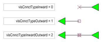
Essentially, this allowed you to graphically manipulate the values of the cells: DirX/A, DirY/B and Type/C that live in Connection Point rows. If you have spent hours looking for this in Visio 2003, and thought you were crazy for imagining things, well, you’re not. This is yet another Disappearing Feature, courtesy of our friends: The Lawyers. The rumor is that this feature was yanked because it infringed on another product’s patent. Anyway, I’ve created a Visio Tool to help you relive the good old days. The downloadable .VSD file contains a special master shape and some Visual Basic for Applications code that lets you graphically manipulate your connections points. I tried to be cool, clever, nouveau, graphic-artsy, etc. and make the shapes 21st-century versions of the old green arrows. Hopefully you’ll find them pleasing to look at. Here’s what they look like:
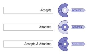
After you download the document, you can run the VBA code to set up your editing session. Just select some shapes and click the big button at the top of the page. You will get a connection point shape dropped-on and linked-to every connection point for each shape you’ve selected.
You can then rotate the shapes to change the connection point’s angle, and right-click to cange the connection point’s type. Just like the old interface! When you’re done, just delete the blue shapes, and your connection points will retain your changes.
As an example, we have a circle and a spike. The spike shape should attach to the circle at any of eight points, and be normal to the circle upon gluing. When we run the VBA code, we get connection-point shapes attached to the eight connection points on the circle, plus the one on the spike. You can then rotate the connection-point shapes, and right-click to change the type. Below, we see all of the shapes rotated correctly, and the spike’s connection-point shape has been changed to “Outward” or “Attaches”, which is type 1.
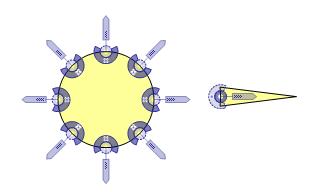
Now, it’s literally a snap (and glue) to attach spike shapes properly to the circle:
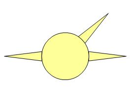
Note: If you see red on a connection point shape, that means that there was a custom formula in the connection point cell. Below, we see that the arrow is red. That is because the DirX/A and DirY/B cells have formulas that match the slope of the triangle.
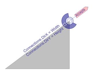
I figured you wouldn’t want my tool to mess up any smart formulas that you worked so hard to create!
Download “Connection Point Configuration Tool”
s!Aj0wJuswNyXlhSxS60-kvqqFZWO7 – Downloaded 4284 times – 103.00 B
The Connection Point tool is very helpful. I am, however, having problems when I add a number of connection points to a shape and then try to connect another shape (to which I have also added a connection point). It seems if I make my connecting shape smaller, it will snap and glue to the first shape. If I make the connecting shape slightly larger (to the size I want), it will not connect. I’ve tried changing the size of your circle and points and see none of the same problems I am experiencing.
Any suggestions are appreciated.
Hi Jerry,
When you glue one shape with connection points to another, it depends on where you grab the shape. Visio tries to find the connection point closest to the mouse cursor, and use that as the point that snaps to the other shape. Try dragging your shape from different points.
– Chris
Jerry,
start a temporary line exactly at the point you want the other shape to snap to. Activate glueing and then drag the other shape over the end point of that temporary line.
*SNAPP* it goes and your shape’s connection point is glued to your temporary line’s end. Then delete the line — and there you go!
I only found out about this solution since I also could not manage to snap or glue connection points of different shapes *to each other* at all (in Visio 2003 that is).
Enjoy,
David.P
I’m trying to use the ConnectionPoint Configuration tool on Visio 2003, SP3. I would like to set the connection points on my shapes so that when a connector is attached to a connection point, the connector line comes out from the shape perpendicular to the tangent to that point (or some angle that I set). (The connector line, when not behaving, comes away from the shape along the tangent or crosses over the shape!)
I’m missing some of the basic usage model for your tool.
1. How to load Connection Point Configuration.vsd
I opened my Visio drawing and Connection Point Configuration.vsd. Each is open in a separate window inside Visio.
2. How to specify the shape whose connection point will be set.
I selected the shape in my drawing. The shape has connection points.
3. How to set the connection point shapes for selected shapes.
3a: I tried pressing the “Show Connection Point Shapes for Selected Shapes” in the Connection Point Configuration.vsd window. I get a popup that says “Please select one or more shapes with connection points!”
3b: I tried right-clicking on my shape. There are no menu items to add connection points.
3c: There don’t appear to be any menu items or taskbar buttons to add connection points. (Actually, there is a menu item under Tools/Macros/Connection Point Configuration/ThisDocument/AddConnectionPointShapes, but clicking on a shape (with connection points) and then on that button doesn’t appear to do anything.
Please help with the above 3 points.
Thank you,
Steve
Hi Steve,
1. The tool only knows how to work with shapes on the same page as the button. You might try copying your shape into the tool document.
Otherwise, go into the VBA editor, make your drawing the active window, select your shape, and run the sub routine: AddConnectionPointShapes.
Or, with your document active and your shape selected, go to Tools > Macro > Connection Point Configuration > ThisDocument > AddConnectionPointShapes
This will create the shapes that allow you to easily configure the connection points.
2. This should now be taken care of.
3. See if this makes sense once you get it running properly.
Hello Visio Guy,
I am fairly new to Visio 2003 and already have a problem I cant solve and hope you can help.
I am creating a process map to open a bank account. At the beginning of the process you can choose between being an individual or if it will be a joint account. When you choose to have a joint account, the process will continue for some time for both choices until you have to enter the information for the second person on the account. How can I show this in my map?
Thanks
I got the connection points vss loaded and have the tool document open. I have a rectangle with some connection points on the left and right sides. I used your tool to set the direction. Actually, as soon as I added the connection points, they pointed the correct directions…the ones on the left point left. The ones on the right point right.
I then deleted the connection points and copied the rectangle back into my symbol. When I placed an instance of the symbol and connected it, all the wires suddenly went the wrong direction, under the symbol in the opposite direction they were supposed to go and then looped around back to the source of the wire!
I looked at the ShapeSheet for the rectangle.
The connection points on the left have:
DirX = -1.0
DirY = 0.0
Type/C = 0
Any idea what’s wrong?
Thanks for your help.
this is amazing. thank you for sharing.
Great write-up. Thanks for your help.
I have a question. The connection points are tiny. Is there a way to increase the size of connection point and change the color.
PS: I am colorblind.
Thanks for your help in advance
Hi Hardik,
They changed a lot of colors and handle shapes for Visio 2013. I don’t know what they were thinking but shape vertices and connection points are almost impossible to see. And you can’t tell if they are selected because they are so small. I don’t know of a way to change the size of them, I doubt that there is a way.
I 100% agree with you. Well, we have to work around it.
Thanks for you reply Visio Guy!
Hi,
Hope someone can point out a problem. I am using Visio 2016.
I have strange issue with connection points not snapping. I want to create a simple rectangle shape that I can use to build grids.
Basically, this rectangle should have outward connection points on the left and top and inward connection points on the right and bottom.
To test, I created 2 rectangles Width: 60 mm and Height: 30 mm
the first rectangle has 2 connection points:
X, Y, DirX/A, DirY/B, Type/C
30, 0, 0, -1, 0
60, 15, 1, 0, 0
The second rectangle also has 2 connection points:
X, Y, DirX/A, DirY/B, Type/C
30, 30, 0, -1, 1
0, 15, 1, 0, 1
When I try to connect one of the rectangle to the other from the right side, it snaps. But when I try to move it from the bottom, it does not snap, or vice versa.
Can anyone suggest what could be the issue?
Thank you in advance.
It’s been a while. How do I load the vsd file into Visio? I opened it, and have a separate window with your demo (in compatibility mode). How do I get it to work in my file?