 You may have noticed cool-looking, shiny ball shapes that pop-up now and again on Visio Guy. They have an attractive offset-radial fill effect, like the balls in the image on the left.
If you’ve played with Visio’s Fill Format dialog, you’ll know that good ol’ Fill Pattern Number 40 will give you a nice-looking radial fill, but there doesn’t seem to be a setting for getting it to be off-center. Well (once again) Visio Guy is here to show you how to work some black magic!
.
.
Computer-graphics and Design-theory Blurb
It seems that in computer-land, or at least Windows-land, there is a semi-standard that says; “The light source comes from the top-left”. Just look at your standard drop-shadows, and the borders on your windows and buttons: they’re dark on the right and bottom, and light on the top and left. I think that’s why the 3D balls look so much better when the “spotlight” is offset. The centered fill just doesn’t seem natural.
Fool the Gradient
The trick to getting this done in Visio is to make the actual shape bigger than the shape that we see. The circle is essentially a smaller window onto a bigger centered-radial-fill. In the shape below, I’ve combined a short diagonal line with a circle, then applied Fill Pattern 40, with a black fill color and a white pattern color:
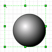
That looks OK, but the tick-mark is distracting. Also, the alignment box (the green-handled rectangle) is bigger than the circle. This makes it hard to resize the circle to a size that we care about.
Fool the Alignment Box
To make this shape perfect, we need to do accomplish two things:
- Make the alignment box match the circle exactly
- Hide the tick-mark
So let’s enter Tutorial Mode now and get this done in a step-by-step manner. First, we need to draw a circle and a line, as shown below:
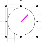
Make sure that the line is inside the alignment box of the circle. We’ll tweak it later, so that we can get our offset fill effect!
Now that we’ve got our two shapes, we need to combine them. That means they’ll be one single shape. Inside the ShapeSheet, we’ll see two Geometry sections: one for the line, and one for the circle. To combine the shapes, simply select them both, the choose: Shape > Operations > Combine from the menu, as shown here:
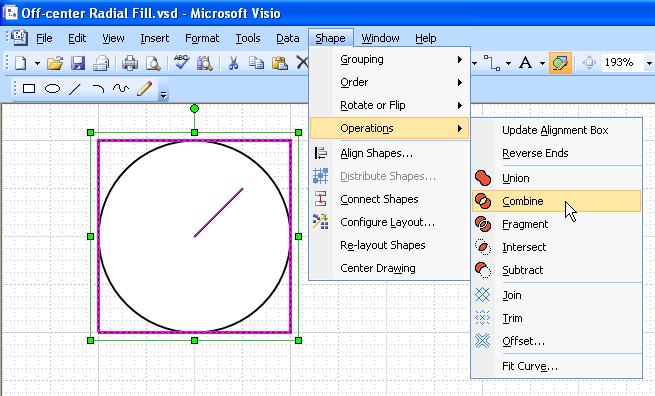
click to view larger image
If you choose the Line or Pencil tool from the Drawing toolbar, you’ll be able to move the vertices of the line segment. But if you move the vertices outside of the circle, the alignment box will grow. This is not what we want, so we need to perform one more trick, using the ShapeSheet.
Select your new Circle-Line shape and choose Window > Show ShapeSheet from the menu. Look for the Protection section and change the value in the cell: LockCalcWH to 1:

If you don’t see the Protection section, choose View > Sections from the menu and check Protection to make it visible.
Now we’ve locked down the alignment box. If you grab a vertex with the pencil tool and move it outside of the circle, the alignment box won’t grow any more! Task 1 is now complete!
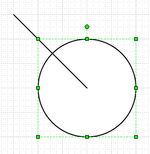
Now we need to make it pretty. Just select your shape and choose: Format > Fill from the menu. Pull down the Pattern drop-down and go way to the bottom, where you’ll find pattern number 40. You’ll have something like this:
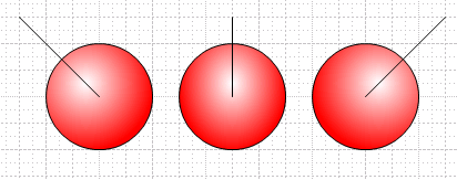
Grab that pencil tool and move the line’s end around to change the lighting effect!
Hide the Line
So the line is still visible and needs to go away. We could simply give the shape a No Line pattern, but that will get rid of the circle’s outline as well. The best bet is to go back into the ShapeSheet and set the GeometryN.NoLine cell to 1.
When you combined the line and the circle together, you created a shape with a single ShapeSheet that contains two Geometry sections. The line section will then be either Geometry1 or Geometry2. The line will be the section that has MoveTo and LineTo rows in it. Find this section.
Once you’ve located the line’s Geometry section, just set the NoLine cell to 1. This will turn off the line’s visibility, and pretty-much completes the shape! If you select the shape with the pencil tool, you’ll still be able to see the vertex and move it around.
Control the Line
If you want the highlight to stay in the same place, then we’re done. But if you want to be able to move it around without having to get the pencil tool every time, then read on!
We can add a control handle to the shape to control the position of the highlight. A control handle is a little yellow diamond that looks like this:
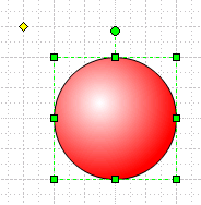
We’ll hook the end-point of the line to the position of the control handle, so that we can easily reposition the light source, whenever we want!
To add the control handle, open the ShapeSheet for your ball, and choose Insert > Section from the menu. Check Controls and click OK. You should see something like this:
click to view larger image
Note the yellow highlights: these are the formulas you’ll have to change. In this case, the line-segment is Geometry2. I’ve renamed the newly-added control handle to “SpotLight”. If you change the formulas in your shape to match those in the yellow boxes, you’ll have a finely-polished (*ahem*), user-configurable, 3D ball Visio shape!
Orbiting a Guide Point
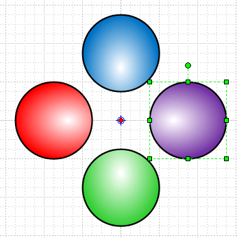
If you drag out a guide point from the upper-left corner, where the rulers meet, then you can do something interesting. You can glue the control handle from your shiny new ball shape to the guide point. The end effect is to create a Sun. As you drag the shape around, the control handle will stay glued to the guide point. Even if you duplicate the ball, the handle will stay glued! This can make for some interesting effects:
Bounding Box Oddities
Another thing that you might notice is that when your mouse is near the hidden line segment, the cursor will change to “there’s a shape under me that you can select” mode, even though the line is hidden. Note the mouse-pointer with the “move-me” cross:
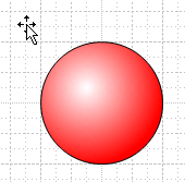
I’m not sure that this is desirable behavior. Perhaps the MS Visio guys ought to log this as a bug an issue. This also effects the selecting of the shape. If you do a net-select, you’ll need to drag the selection rectangle around the circle and the control handle – you have to get it all in order to select the shape. I guess it’s easier just to click it!
When you paste the shape into other apps, you might get an object that is as big as the circle-plus-hidden-line as well. When pasting into MS Word 2003, the Visio object was larger than the circle. If I pasted as a metafile or a bitmap, the result was a “tightly-enclosed” circle. Excel is a bit more clever, apparently: it gets it right for all three. You get a tightly-enclosed ball whether you paste as a Visio object, a metafile, or a bitmap.
Well, we hope you’ve had fun with this tutorial, and learned a bit more about creating Visio shapes. You’ve learned about the Combine operation, adding control handles to shapes, and hiding geometry via the NoLine cell. We’re eager to hear the clever ways in which you’ll surely use this knowledge, so let us know!
Download “Off-center Radial Fill Effect”
s!Aj0wJuswNyXlhXmxDI6N2Hpb9XbK – Downloaded 4165 times – 103.00 B

Hi,
Great website. Great tutorial on fill effects, but I am confused on one point.
When I go to ShapeSheet (I hadn’t even know about this), I get different sections. Sometimes I see protection, and sometimes I don’t. There seem to be more than one type of ShapeSheet.
Thanks.
Stanley
Hi Stanley,
Sometimes sections can be hidden, via View > Section in the ShapeSheet window.
Some shapes have sections that others don’t, due to slight differences in shapes. For instance, 1D shapes (like connectors) have a “1-D Transform” section that other shapes don’t have. And groups often don’t have any Geometry sections.
Also, a developer can add User-defined rows, Shape Data fields, Actions (right-click menu items), Smart Tags, Scratch rows, etc. to a shape, which will change the visible sections in the ShapeSheet.
So view options, shape type, and developer-customization can all have an effect on how the ShapeSheet appears.
Cheers,
– Chris
Hi Visio Guy,
Thank you for your reply.
Actually, shortly after I left my comment, I noticed that the sections that I got depended upon whether or not any object was selected. When I had the ball selected, I got the ShapeSheet shown in your tutorial. When I had nothing selected, I got a different ShapeSheet.
Great tutorial. I intend to spend much time studying your website. It is a real contribution to knowledge.
Stanley
Wonderfull, I was looking since long time, how to do it, now I got solution, many thanks.
I have another question, is it possible to distribute shape or line in round ?, mean’s to have a good repartition around a circle, like a clock by example ?.
Many thanks
Pierre
Hi Pierre,
There is some VBA code for arranging shapes in a circular pattern on this site: http://visio.mvps.org/VBA.htm
Just search for “Polar Array”.
If you are able to work with VBA code, this might help you.
Thanks,
I work a little bit with VBA, but principaly with excel, I will try with Visio, we will see….
But anyways,
Thanks.
Regards
Pierre
you’re Awesome…
Thanks Chris. Another great article : )
In case anyone wants to have the control moves the *center* of the highlight directly, then the following formulas will do:
Controls.SpotLight.X = SETATREF(Geometry2.X2,SETATREFEVAL((SETATREFEXPR(Width*0.5)-Width*0.5)*2+
IF(SETATREFEXPR(Width*0.5)>Width*0.5,Width,0)),TRUE)+SETATREFEXPR(Width*0.5)
Controls.SpotLight.Y = SETATREF(Geometry2.Y2,SETATREFEVAL((SETATREFEXPR(Height*0.5)-Height*0.5)*2+
IF(SETATREFEXPR(Height*0.5)>Height*0.5,Height,0)),TRUE)+SETATREFEXPR(Height*0.5)
Yousuf.
Awesome tip, Yousuf, thanks!
I think that this could be done without SETF/SETATREF functions, but I’d have to set down and think about it for awhile 🙂
This no longer appears to work in Visio 2013 8(
Can you help to fix to make this work in Visio 2016 ?
Finally figured out how to rebuild this in Visio 2013 and pretty sure it will apply to Visio 2016.
in addtion to Protection.LockCalcWH = 1 and Geometry2.NoLine=True, one needs to make the following modifications
set Gradient.UseGroupGradient to Guard(True);
Fix the Line Start to the Center of the boundbox.
set Geometry2[1].RelMoveTo.X to Width*0.5;
set Geometry2[1].RelMoveTo.Y to Height*0.5;
Keep the invisible line matched to the SpotLight thereby ensuring placement of the offset.
set Geometry2[2].RelLineTo.X to Controls.SpotLight
set Geometry2[2].RelLineTo.Y to Controls.SpotLight.Y
Optionally
Gradient.RotateGradientWithShape to Guard(True) for best effect especially if using Rectangle or Linear gradients.
Thanks for working this out abyssoft!
In Visio 2013/2016 you can flip row types between MoveTo and RelMoveTo or LineTo and RelLineTo. Right-click a cell and choose Change Row Type.
With the “Rel” variants, you don’t need to type Width* or Height*, just the coefficients. As soon as you need any bit of complexity, it usually pays to switch away from “Rel” and use the older row types.
Example:
LineTo = Width*0.75
RelLineTo = 0.75
So in your code above, it should probably be:
Geometry2.X1 > RelMoveTo = 0.5
Geometry2.Y1 > RelMoveTo = 0.5
The way you have it will work if the shape happens to be 1 in x 1 in, but as soon as you stretch it, the Width*0.5 will run away from the center very quickly! 🙂
VISIO 2013/2016 SOLUTION!
If I ever get more free time, I’ll make a new article. Anyway, I took abyssoft’s lead and checked this out.
In the new versions of Visio, there is a second gradient system that has to be activated. It allows for multi-gradient stops, and other advanced features.
I found that changing these cells will do what you need:
[Gradient Properties]
// Radial pattern:
FillGradientDir = GUARD(3)
// These two seem to say; “Use Visio 2013-style gradients!”
FillGradientEnabled = GUARD(TRUE)
UseGroupGradient = GUARD(TRUE)
[Fill Gradient Stops]
// Color white:
FillGradientStops.GradientStopColor = GUARD(RGB(255,255,255))
FillGradientStops.GradientStopPosition = 0%
// Color red:
FillGradientStops.GradientStopColor[2] = RGB(255,0,0)
// 95% gradient stop seems to work better than 100%
FillGradientStops.GradientStopPosition[2] = 95%
Also, for fun, try this:
FillGradientDir = GUARD(13)
This is a “path” style gradient. I still don’t know exactly what it is supposed to do, but it makes a nice effect–but if you go too far with the control handle, it freaks out.
And this set of gradient stops puts a highlight, and a backlight on the circle for a nice effect:
FillGradientStops.GradientStopColor = GUARD(RGB(255,255,255))
FillGradientStops.GradientStopPosition = 0%
FillGradientStops.GradientStopColor[2] = RGB(255,0,0)
FillGradientStops.GradientStopPosition[2] = 50%
FillGradientStops.GradientStopColor[3] = GUARD(RGB(255,255,255))
FillGradientStops.GradientStopPosition[3] = 90%
FillGradientStops.GradientStopColor[4] = RGB(255,0,0)
FillGradientStops.GradientStopPosition[4] = 100%
Note: the colors go white-red-white-red.
Also: if you GUARD the whites, then you can use the regular Fill color drop-down to change the color of the shape!
The effect looks great within Visio. However, if the shape(s) is exported to pdf or svg, Adobe Acrobat (and also Illustrator) still sees the line that is supposed to be hidden. Could you suggest how to fix so that Acrobat (and also Illustrator) does not show the line that is supposed to be hidden ? Many thanks !