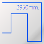
 If you use Visio to create scaled plan views that include electrical equipment, you may have a need to rough-out actual, to-scale cable paths–and even get accurate estimates as to how much cabling you’ll need. This article explores just how you can go about it!
I have done work for the fine folks at D-Tools for many years. They make a product called System Integrator (SI) that helps in the estimation, design and project management of low voltage systems, such as audio-visual systems, home networks, and high-end conferencing systems. The software has a visual component that can run in Visio or AutoCAD, which is where I come in from time to time.
While I am not an expert in the details of what SI and its users are up to, I’ve got just enough engineering sense to be dangerous. It seems to me that SI users and other technical types might want to detail cable layouts in plan views that they’ve created in Visio. So let’s see how we might create a simple cable shape that can display its total length.
Overview
The general process for creating such a cable shape is as follows.
- Draw a cable with right-angled bends
- Insert a text field that can report the length of the path
- Tweak the dynamic expression for units and precision
- Move the text block
Depending on your level of expertise, some of these steps might be obvious, while others might seem mysterious. In the following sections, I’ll dive into the details of each phase. Hopefully you’ll pick up a useful trick or two, and add a new skill to your toolbox!
One more note before we start. This article makes use of the PATHLENGTH ShapeSheet function, which appeared in Visio 2010. If you have an older version, the technique for displaying the path length won’t work. You may find the tips on drawing and editing a path useful, and the general methods for inserting dynamic text fields interesting as well.
Set up a Scaled Drawing
Since our cable shape will represent a wire in the real world, we’ll want to do our drawing on a scaled page. Typical Visio diagrams such as flowcharts, org charts or logical network diagrams have “no scale”, or 1:1. But Visio supports drawing scales, so you can work in real-world units, which is great for drawing plan or elevation views of physical spaces.
You could easily get going with a scaled diagram by opening one of Visio’s built-in, scaled templates, such as:
- Floor Plans > Floor Plan
- Floor Plans >Home Plan
- Floor Plans > Office Layout
- Floor Plans > Space Plan
- Network > Rack Diagram
But let’s start from scratch, so that you have the chance to learn a few more tricks:
- Open a new, Blank Drawing:

- Right-click the “Page-1” page tab at the bottom of the Visio window, and choose Page Setup…
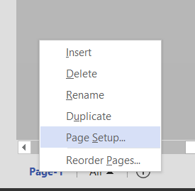
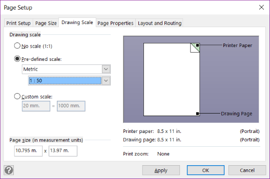
- Go to the Drawing Scale tab.
- Click Pre-defined scale.
- Select an appropriate scale for the plan view of a room or building, for example:
Architectural, 1/4″ = 1′-0″
or
Metric, 1:50
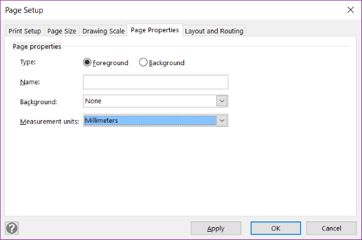
- Go to the Page Properties tab, and set the units for your drawing.
- Back in the main ribbon, go to the Design tab, and turn off the (sometimes maddening) Auto Size feature, and set the Orientation to Landscape:
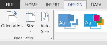
You can verify that you are indeed working in a scaled environment by grabbing a drawing tool like the Ellipse, Line or Rectangle tool. You’ll find these in a drop-down control in the top-right corner of the Home > Tools ribbon group.
Then draw any ol’ shape on the page. If you look at the status bar at lower-left, you should see that a shape that appears to be a few centimeters wide on the page, is “actually” thousands of millimeters long!
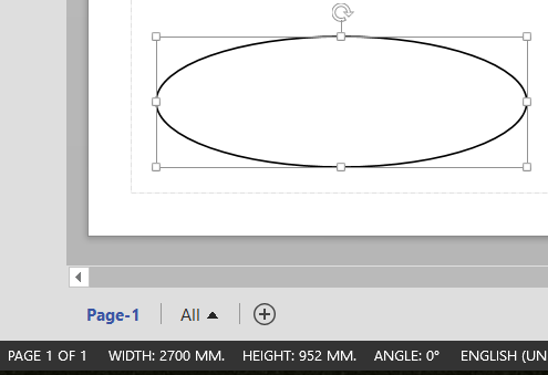
A quick look at the status bar verifies that we are indeed working with a scaled drawing
Drawing and Editing the Cable Shape
You could use the Dynamic Connector to draw a cable shape. It arguably has nicer features for adding bends–especially right-angled bends, and its endpoints glue nicely to shapes and connection points. However, connectors have a habit of occasionally re-routing, or trying to avoid other shapes on the page. Because of this, you might end up fighting the connector more than you benefit from its user-interface advantages.
So we’ll use the Line Tool to create a static cable path, and we’ll learn a few tricks for controlling it and editing it.
- Get the Line Tool from drop-down control in the Home > Tools ribbon group.
- Click and drag to add segments. Note: don’t “click and click” like in some CAD programs.
- Hold down the Shift while click-dragging to constrain your paths to horizontal, vertical or 45-degree diagonal segments.
- You can insert vertices along the path by holding down Ctrl and clicking (while using the Line, Freeform, Arc or Pencil tools).
- You can edit existing vertices by first clicking them to turn them red, then dragging them. You press Shift while selecting vertices to select more than one.
Note that the Shift-constraining doesn’t work when inserting and editing vertices. - You can delete vertices by selecting your path (with the Line, Freeform, Arc or Pencil tools), clicking a vertex so that it turns red, then pressing Delete.
Note: in Visio 2013 and Visio 2016, vertices are VERY hard to see – they are small, dark blue points. If you don’t see them at first, make the line a color other than black. They’ll be easier to spot. - You can add corner-rounding to the shape. In Visio 2013/2016, press F3 to get the Format panel, expand the LINE section, then choose one of the Rounding presets, or enter a numerical Rounding size.
- You can prevent corner rounding at select vertices by Ctrl+clicking to add a second vertex on top of an existing vertex.
- You can turn straight lines into bowed arcs by using the Pencil Tool. Select a path, then click the mid-point handle. (Again, very hard to see in Visio 2013/2016…). When it turns red, click-drag to a new position to get a circular arc.
Here’s a path that shows many of the features we’ve just described:
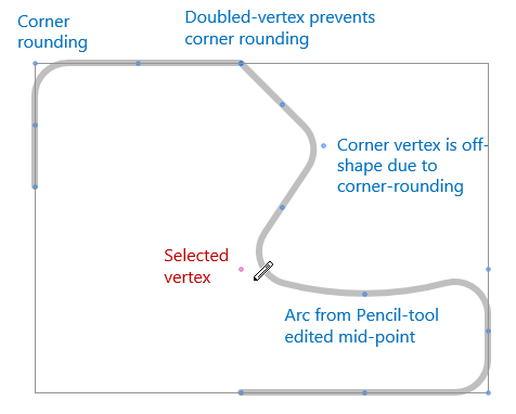
Note, you can turn on the grid (View > Show > Grid checkbox) to help make things straight while editing. Remember that the Shift constraint that works when drawing doesn’t work when editing vertices, so the grid or even ruler guides can help here.
You should now have a nice cable path. Ideally you would draw this on some sort of plan-view diagram to connect electrical outlets, data ports, computer and A/V equipment, etc. Since we are using the drawing tools to draw actual vectors, we will end up with what is called a “2D” shape in Visio parlance. The end points of our cabling shape can’t really be glued to connection points or equipment shapes. That is one drawback of this technique, hence the word “simple” in the article’s title.
Labeling the Cable Shape
Now we need to add some text to the shape to show how long it is. Here are the basic steps:
- Select your cable shape
- Type “Length: “.
You only need to select Visio shapes and start typing to add text! - Go to Insert > Field on the ribbon
- Select Custom Formula in the Category list
- Enter PATHLENGTH(Geometry1.Path) in the Custom formula text box
- Hit OK.
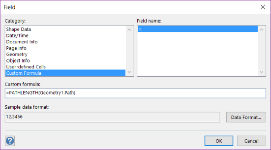
The Insert > Field dialog, with a Custom Formula in the works
You should see the length of the shape displayed as text. Stretch and shrink the shape, or use the Line Tool to move the shape around, or to add, delete vertices. The displayed length value should change as you do this.
A good test case is to draw almost a complete rectangle. Then you can view the Width and Height values in the status bar, add them together, then double the result. This should be very close to the displayed length of the cable.
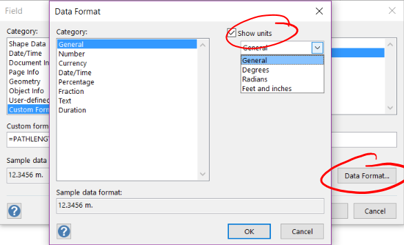
Bug! In my case, I had set the page units to millimeters, yet the displayed length appeared to be in inches! Now, Visio’s internal units are inches, so this is somewhat understandable. So I then tried to explicitly tell the inserted field to display its units.
To do this, I clicked the Data Format… button on the Field form, and explicitly chose to Show units, but nothing changed–no units were displayed in the text! Choosing the Number category offers more options for formatting, including number of decimal places. But for some reason, these had issues too (in both Visio 2013 and Visio 2016.)
The Insert Field and Data Format dialogs let you specify units and precision to display for numerical quantities, but they don’t work properly with the PATHLENGTH function
It turns out that the PATHLENGTH ShapeSheet function (which we used for our Custom formula in the Field dialog), doesn’t seem to be returning units, as a length function should. For this reason, you shouldn’t rely on the Field and Data Format dialogs for formatting the value.
Instead, we’ll exert complete control over units and decimal places by modifying our custom formula in the next section.
Editing the Inserted Field
So we’ve got a two-part text block on our shape. It has static text that we typed (“Length: “) and a dynamic text field that reports the length of the shape–but may not be showing the value exactly as we want to see it.
So let’s return to the custom formula and expand upon it. The best way to edit the field is to do this:
- Enter text-edit mode. You’ve got several choices:
- Double-click the shape. This works for most Visio shapes, unless they have special behaviors for double-click, or have text-editing locked down.
- Select the shape, the press F2.
- Select the shape, then get the Text Tool from the Home > Tools group.
- Select the shape, then get the Text Tool via the keyboard shortcut Ctrl+2
Don’t select the shape and start typing. This will blow all the text away, including your “smart” field.
- Select just the inserted-field portion of the text. The whole block of numbers should easily highlight.
- Return to Insert > Field. Tip: Ctrl+F9 will get you there more quickly!
All of the appropriate items should already be selected in the Field form: Category = Custom Formula, Custom Formula = PATHLENGTH(Geometry1.Path) - Click Data Format… and make sure you have unchecked any options to “Show Units” – it will conflict with our experimentation in the coming paragraphs.
- Edit the formula, then press OK to update the dynamic text on your shape.
Let’s try out a few edits to that custom formula.
We can force the units that we use by adding zero of some unit before the formula. This will cast the value, regardless of the page’s or shape’s units of choice:
- 0m + PATHLENGTH(Geometry1.Path)
- 0cm + PATHLENGTH(Geometry1.Path)
- 0in + PATHLENGTH(Geometry1.Path)
That’s right! You could convert a Metric value to an Imperial value, or vice-versa. Maybe we could even display both in the same text block (hint, hint!).
You can force the units to be those of the drawing page by actually referencing the page’s drawing scale:
- 0*ThePage!DrawingScale+PATHLENGTH(Geometry1.Path)
By the way, when I used this expression, the “Show Units” option that I had checked earlier finally worked, and “mm.” was appended to my dynamic text field.
Here are some variations in the formula, along with associated sample text
- FORMAT((0IN+PATHLENGTH(Geometry1.Path)),”0.## uu”)
Length: 460.24 inches - =FORMAT((0IN+PATHLENGTH(Geometry1.Path)),”0.000UU”)
Length: 460.244INCHES - =FORMAT((0IN+PATHLENGTH(Geometry1.Path)),”0.000 u”)
Length: 460.244 in. - =FORMAT((0M+PATHLENGTH(Geometry1.Path)),”#.## u”)
Length: 11.69 m.
The shorcut Ctrl + F9 is really coming in handy for doing all of these field editsFORMAT and PATHLENGTH are Visio ShapeSheet functions. The ShapeSheet is an interface, similar to Excel, which sits behind Visio shapes to enable sophisticated “SmartShape” behavior. You’ll find more useful information related to formatting strings in the Visio devloper ShapeSheet reference online:
- FORMAT ShapeSheet Function
https://msdn.microsoft.com/en-us/library/office/ff768446(v=office.14).aspx - FORMATEX ShapeSheet Fnction
https://msdn.microsoft.com/en-us/library/office/ff768446(v=office.14).aspx - About Format Pictures
https://msdn.microsoft.com/en-us/library/office/ff768446(v=office.14).aspx
Moving the Text Block
You can move the text around the shape by using the Text Block tool. You’ll find it on the ribbon in the Home > Tools group. Or just hit Shift + Ctrl + 4.
When you select a shape with the Text Block tool, it might appear that nothing is happened. That is because a shape’s text block has an alignment box that matches the size and orientation of the shape by default.
But you can drag the handles at the edges of the text block and make the text block more closely match the text.
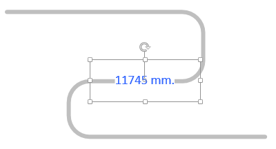
This text block has been resized to more closely match the size of the text.
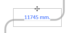
Then, you can click the mouse when it is over the edge of the text block’s alignment box, and drag to move the text around. Note the crosshairs cursor that appears when the mouse is in the correct position:
Ultimately, we should use a convention you’ll find on many Visio shapes, where a Control Handle is added to the shape for moving the text around. This is a convenience that saves you the trouble of getting the Text Block tool. But it is something that a shape developer needs to explicitly add to the shape. Remind me to write an article on that topic!
Last Notes
Visio Professional editions have the ability to import AutoCAD drawings. This is a great feature for getting floor plans or scaled elevations into Visio quickly, and at-scale.
Then you could draw to-scale cable paths over the imported drawing, and possibly generate a cabling report.
The report would be easier to create if the length of each wire was stored in a Shape Data field. This is partially possible through Visio’s normal user interface, but would require some ShapeSheet editing to get it right.
To avoid moving shapes in the drawing, a plan view page could be assigned as a background page of a cabling page. This is effectively like placing a sheet of glass over the plan view, then drawing the cables on top. No danger of accidentally selecting shapes while you trace out paths.
Alternatively, shapes can be placed on layers, and those layers can be locked down. This is another way to avoid accidentally moving shapes.
And the cable shapes themselves could be placed on a “cabling” layer, that you could lock once complete, or even hide when you don’t want to see all of that spaghetti!

Old post, but very useful. Thank you very much!
It would be even more interesting if we could put a summary on the page that shows total cable length per cable type (different cables in different colors or layers or different label, what is most simple).
Hi Dries,
That would probably require code, such as an add-in or VBA macros, unless the built-in Visio reporting can somehow do the totals. The more I think about it, the reporting probably can do this, but the shape would need to have a Shape Data field to hold the total length, as well as some sort of Category field.
Or to get the units correct, in the ‘Field’ box you could select Geometry and width, and in the Data format, select ‘Show Units’
Hello ,
Very nice notes …
Use Visio for a long time but at low level
Now i apply your formula length on a single line for testing and he return 118,122 , while the size & position report length 300 .
Try to play with the page scale , nothing work .
Can you help ?
Best regards … and again nice job you doing .
At last succinct information how to measure the free form length in Visio.
Hint to William: 300/118=2,54