Attractive, realistic-looking Visio equipment shapes don’t have to be heavy and inefficient.
In this article, we’ll look at some innovative A/V equipment shapes from D-Tools that offer the win-win scenario of good-looking and light weight.
We’ll tear these SmartShapes apart and show how you can use custom line patterns and creative shadow techniques to add pizzazz to your shapes, without adding bloat!
Beauty and Intelligence: Mutually Exclusive?
Ah yes, the ShapeSheet giveth, and the ShapeSheet taketh away.
Visio SmartShapes offer a wonderful vehicle for delivering powerful graphical objects with built-in intelligence without code. But the complexity of the ShapeSheet also adds bloat to even the simplest of shapes.
So in the quest to keep file size down, and performance up, Visio shape designers often shy away from adding too much detail to their SmartShapes. Yes, we can hear the Adobe Illustrator guys over in the Art Department snickering, and see them looking down their noses…
But if we dip deep enough into our cauldron of Visio Black Magic, we can often find choice morsels to help us fight back!
And in today’s case, we get some really cool effects without using the ShapeSheet at all, so just about anybody can take advantage of these techniques!
A Fine Speaker is a Work of Art
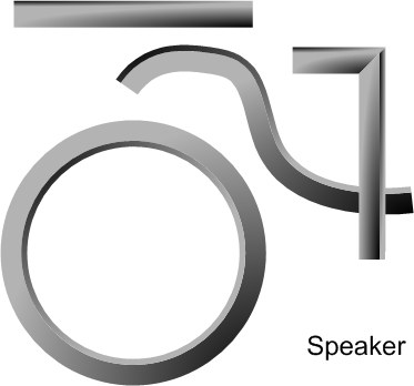
Take a look at this good-lookin’ speaker shape, which you’ll find on the Speakers stencil that comes with D-Tools System Integrator 5:

It’s a pretty attractive-looking speaker: it might even qualify for the Visio Art Page! And if you have a high-res printer, it looks even better. But since we’re stuck in 96-dpi-monitor-land right now, we’ll just zoom in to give you a better look:

Well, those are some mighty attractive speaker shapes! Not bad for a “flowcharting app, business graphics” application, eh?
When I first saw these shapes, my “expert eye” told me that the woofer and tweeter were both composed of at least four circles, each with fancy gradient fills.
Although eight is not a huge number, that many separate shapes could start to get unwieldy if you have to protect and guard formatting or enter smart formulas to control sizing.
I also suspected that the cool shading effects might require my complicated, yet attractive Off-center Radial Fill Effect technique.
Well it turns out that I was wrong.
Keep It Simple With Two “End-user” Techniques
A graphic artist (aka: young whippersnapper) at D-Tools is clearly smarter than I (although I can probably still out-do him in calculus…) He was able to create the woofer and tweeter much more simply, using just two circles for each unit!
He did this using clever application of two formatting features:
- Magnified shadow
- Custom line pattern
Both of these techniques are readily available to end-users. Custom patterns are a bit more hidden than shadowing, but neither feature requires ShapeSheet development or programming to achieve.
If you’re not familiar with these techniques, I can offer some resources that will help get you up to speed:
I’ve talked before about using shadows to squeeze more formatting and color into a single shape in this article: How Many Fill Colors Can You Put on a Visio Shape?
And if custom patterns are new to you, you can find out more about them by perusing these articles:
- Developing Visio Solutions: Chapter 10
- Release the Power of Visio Custom Line Patterns
- Smart LineWeight: Bigger Shape, Thicker Lines
- Bubble Revision Shapes
So let’s move along and show how these two techniques were used to create those nifty-looking speakers!
Custom Line Patterns
It turns out that you can create custom patterns that contain gradient fills. At one time in Visio’s history, this was not allowed, but it seems it works just fine in Visio 2007 (and Visio 2003)
Our friend at D-Tools created the “Bevel2” pattern, by creating a simple rectangle, filled with pattern #31. Pattern 31 creates a fill that gradates from the top-left corner to the lower-right.
Here we see the custom line pattern highlighted in the Drawing Explorer tree, as well as the actual contents of that pattern:
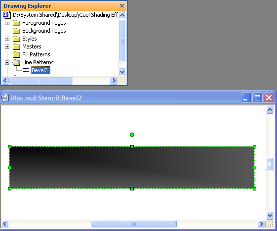
Once the line pattern is created, you can apply it to any shape using the Format > Line dialog.
Custom patterns are listed at the bottom of the Pattern drop-down list. Here’s what Bevel2 looks like when it is applied to various curves. I’ve applied a generous line-weight to help you see what’s going on:
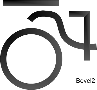
In our speaker shapes, Bevel2 is used as the second-outermost ring on the speakers, not the outermost ring. If you look closely at the speakers at the beginning of this article, you’ll see Bevel2 just inside the really big, outer bevels.
Using similar techniques, several other custom line patterns are used to illustrate the various components of D-Tools equipment shapes. Here’s a sampling of them:
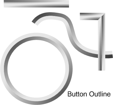
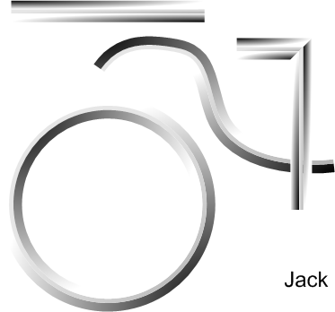
You can imagine these patterns being used in a variety of ways to create some really good-looking buttons, knobs, bezels, frames, switches and other gadgetry that make up A/V equipment!
Magnified Shadows
Starting with Visio 2003, the shadow characteristics of Visio shapes were really opened up and made more flexible. Shadows can now have different sizes, shapes, and projections.
In the right hands, these shadow options can be cleverly manipulated to create effects that look nothing at all like shadows. One such technique was used to create the outermost edge of our example speaker shapes.
Below, we see the Shadow Settings dialog for one of our speaker shapes:
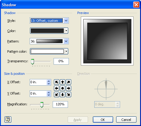
It’s important to note the following settings for this shadow:
- Style = Offset, custom
- Offset = (0, 0)
- Magnification = 120%
- Pattern = 36
So this shadow has zero offset, which means it sits directly below the shape. But it has a 120% magnification, which means it is bigger than the shape itself. And this extra size projects equally in all directions because of the (0, 0) offset. Therefore, we end up with the outer-bevel effect that we see in the speakers!
The first time I saw this, I smacked myself repeatedly, uttering the words; “Why didn’t I think of this” over and over and over.
Gradient Fills
The center bits of each speaker use standard gradient fills. This is nothing earth-shaking, but I thought I’d mention it here, just for completeness:
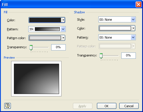
The centers of each speaker shape use some form of corner-radius gradient fill to get that bulbous, protruding effect. This can be achieved using fill patterns 36, 37, 38 or 39 .
Putting it All Together
To better understand the process of creating our speaker shape, let’s how the shape evolves as we apply each effect:
|
|
1. Draw a simple circle, with thick, black line |
|
|
2. Apply our custom line-pattern “Bevel2” to the circle. |
|
|
3. Apply fill pattern #39 to the circle to create a 3D effect for the speaker cone. |
|
|
4. Apply the magnified shadow effect. 120% magnification with zero-offset. This forms the outer edge of the speaker. |
|
|
5. Add the center circle. This is simply a smaller circle shape, with fill pattern #36 applied. |
I hope you enjoyed reading about these techniques, and I hope you put them to use in creating your own SmartShapes. Let us know what wonders you come up with, we’d love to share!







Very nice. Pretty too!
Hey VisGuy,
Thanks for the props. It is always nice to have your work recognized by an expert. I think a lot of our users just take this kind of functionality for granted. Your readers may also want to know about the Line Weight formula in the speaker shape, LineWeight:=Height*0.02*User.AntiScale. This allows the bevel size to re-size intelligently with the height of the master shape so this one shape will look “right” no matter what the size. Lets see the Photoshop/Illustrator geeks top that!
Thanks for pointing that out, Adam! My articles tend to get too long, so I’ve been trying to cut out details. Your comment reminds me that this web site could use a few articles about sizing and scaled drawings.
– Chris
Speaker Stencil no longer exists.
The info metal mentions should be moved to the top of the article.
“Speaker Stencil no longer exists”, you mean in the latest D-Tools release of SI?
I think the technique in this article might also have issues in Visio 2013. I don’t have time to research it right now, but maybe someone can chime in if they know for sure.
Hi,
I need some help in understanding how to copy a let us say a milestone shape from the timeline stencil and have this shape when moved to the swim-lane to drop at a particular vertices related to the timeline and based on external data from an excel workbook.
I am a bit confuse about how to set the values in the shapesheet to make the milestone take the value from a column of excel external link data and display the project activity and ensure the color to change to green when the activity is completed.
A documentation could not be found on the net so far unless you may direct me to one.
Regards,
Chuck
Hi Chuck,
Not really sure how your question relates to this article, but anyway…
There is no syntax to directly link from the ShapeSheet behind a Visio shape to an Excel workbook. While they look similar, they are separate systems.
You can link Shape Data fields in shapes to external data sources using the old DataBase Wizard, or using the newer data linking capabilities that appeared in Visio 2007 Professional, and continue in Visio 2010 Pro/Premium and Visio 2013 Pro.