 Visio network shapes have gone “3D”, but Visio connectors have decidedly not…
…unless you’re the guys behind the creation of the Zeus ZXTM Appliance Network Stencil. Several readers have noticed the cool isometric connectors that the KnowledgeHub guys used in their sample illustration, and want to get ‘hold of ’em.
We’re not sure where the KH folks got those connectors, but a little light bulb went * bing * inside our Visio Guy heads as we remembered yet another an unfinished prototype gathering dust on our HD. Ah yes, Oblique Connector.vsd, from long, long ago…
Yes, we dug-up and dusted-off the old prototype and produced a finished shape that lets you connect 3D, or isometric looking shapes with connectors that match. In today’s download, you’ll find this master:
![]()
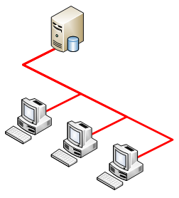
Which lets you create illustrations that look like this:

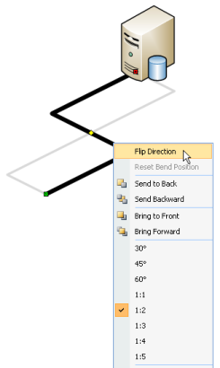
If you right-click on the connector, you’ll see a BUNCH of options:

Let’s briefly go over the menu items and other features of the shape:
Flip
The first menu item is Flip Direction. This changes the “S” orientation of the connector by 90 degrees (in our projected world…) In the illustration above, you can see the light-gray line represents what the black line would look like after this flipping operation.
Reset Bend Position
This sends the bend back to the middle position. You can reposition the bend by tugging on the little yellow control handle in the middle of the shape. But if you want to get a bunch of connectors to line up, like they are in the first illustration up top, it’s best to get the bend back to the default position. Note, if the bend is already there, then this menu item will be disabled.
Z-order
The items are self-explanatory, but the point is this: it’s easier to send the connector behind the computer, then to try to adjust connection points so that they’re just on the edge where the connector meets the shape.
Angle and Slope
You can change the perspective of the connector by choosing one of the slope settings. 30°, 45° and 60° settings are probably pretty clear – the connector lines will follow those angles. For the other “ratio” settings, the numbers simply indicate how much the connector lines run horizontally versus how much they rise vertically. So the 1:3 setting means the connector goes over three units and up one unit. The 1:1 setting is the same as 45°.
Visio’s snazzy 3D network shapes appear to be drawn as true isometric projections. That means their lines run at 30° from the horizontal. So our connector should technically use the 30° setting to match the angles of the network shapes. We’ve found, however, that the setting 1:2 is very close to 30° (it’s 26.6°…) works very well, because it’s easier to position the network shapes in 1:2 increments by snapping to the grid.
Edit via Custom Properties / Shape Data
You can also change the flip direction and the slope of the connector via Custom Properties (Shape Data). Just show the property-editing window via View > Shape Data Window (in Visio 2007) or View > Custom Properties Window (in Visio 2003) and you’ll see the fields just waiting for your input!
Dynamic Glue
Normally, as you connect shapes in Visio, you get that neat-o red rectangle that indicates you’re making a dynamically glued connection. With dynamic glue, a connector will automatically wander around the perimeter of a shape, finding the best place to which to connect.
We tried to implement this feature on the Oblique connector shape, but it just wouldn’t work. It seems that Visio’s Dynamic connector gets lots of special treatment from the engine. This treatment had the effect of hammering our carefully crafted ShapeSheet formulas and making the connector do scary things.
Download “Oblique Connectors (Visio 2007 version)”
s!Aj0wJuswNyXlhwV5v8gHAwu2Frnx – Downloaded 24005 times – 103.00 B
Good work, Chris!
Saved me hours of work, really, my kid thanks you for this ;), great work. Now a question, how can I build 3d objects in visio (or for visio)? I need to do some basic drowing in 3d and I didn´t find anything close to what I need in the the shape library.
Mauricio
Great work, thanks.
Thanks for this – most helpful!!
Hey Guys,
Thanks for the positive feedback. Glad the shapes helped you out!
– Chris
Do you know where I can find oblique Cisco shapes?
Hi Brian,
I don’t know of any oblique Cisco shapes off-hand. Have you looked at Visio Cafe? or maybe even the Cisco site itself? Probably, you’ll mostly find shapes that are straight-on elevation views, but good luck!
– Chris
Brian — As Visio Guy said, check out Visio Cafe. Go to the VSDfx section…there you’ll find Cisco 3D images. It’s only a handfull of models at this point, but it’s a start!
Shameless plug time… we also have some Isometric connector shapes in the VSD Grafx collection on the Visio Cafe that are located in the VSDfx-Essentials-3D.vss stencil. We threw in some Isometric arrows as well. Keep your eyes open for more stuff Isometric shapes in the future – we’ve just gotten started!
Trevor Foster
VSD Grafx Inc.
Hey Trevor,
No shame about plugging! You’ve got some real cool stuff on Visio Cafe, and should be proud of it.
I really like the Isometric Arrows you guys posted!
– Chris
Is there any way to make these connectors ‘jump’ over eachother like the default connector objects in Visio?
Hi Jason,
Good idea.
These connectors are hand-built and don’t use the built-in auto-routing capabilities that Visio has. Unfortunately, line jumps are part of that functionality. I tried implementing some of those features in these connectors, but Visio ends up taking over the shape and blasting the isometric/oblique geometry.
So it doesn’t work.
A work-around is to create a custom line pattern that has a black line surrounded by white on both sides. This has the effect of making crossing lines look like they have a gap-style line jump.
For more on custom patterns, see our “custom pattern” tagged articles:
http://www.visguy.com/tag/custom-patterns/
– Chris
Thank you!!!
It’s exactly what was looking for.
Thanks again for saving me hours of time
Can anyone explain the difference between line jumping and not line jumping. Does it make a difference, is there an actual rule.
I get this error, I became a memember of the forums… Is there another membership I need, if so, how can I be considered?
You must be logged in to download this file.
Thank You
Dean
Hi Dean,
The accounts for the forum and Visio Guy site are not the same. The last time I checked into this, the bridge between WordPress and the SMF forum software didn’t seem up to snuff.
The blog and forum plug-ins have come a long way since I’ve started this though, so I should try to get to this in the near future.
Sorry for the extra run-around,
– Chris
Good Site and content.
Keep up the good work.
They look awesome, but I can’t download them. It says ‘You must be logged in to download this file’.
Hi Knifey,
I made some updates that removed the link for logging-in or registering. They are back again, or you can just register here
Your download link still requires login.
Hi VT,
Yes, you have to register to get some of the downloads on this site. The login screen contains a link to register as well.
I just downloaded the Oblique connectors and anxious to see how they work with the 3D shapes.
I’ve been browsing for hours looking for 3D shapes of some specific telecom/network/buildings I need to use in my Telecom Diagrams like Radio Tower, Satellite Dish, Office Building, small hub or point of presence, stadium, and other landmark buildings.
I already searched in the Visio Cafe (great place!) with no luck. I hope you can help me.
Other problem I can’t seem to solve, I used first the demo Visio who had a very useful “measure” shape tool for floor drawings where it inmediately gave the measure of whichever element on scale. Now that I got the CD purchased that shape is gone. Any idea where to find it?
Regards
Fernando
Can I edit existing dwgs with this? Do I have to open this file to start a dwg using this?
Thanks
I have looked through all of the Isometric/Oblique posts on this site and others and I’m wondering if anyone has created a flowchart “decision” shape (diamond)? I’m aware of the Isometric shapes that Vojo has posted but I don’t seem to be able to manipulate/skew shapes such as the cube to look good as a diamond within an isometric layout. Any help would be appreciated.
Is the VSDfx-Essentials-3D.vss still available on the Visio Cafe site? I only found an archived post but cannot find the stencil for the Isometric connector shapes.
Good stuff by the way.
I could download the file many times but still unable to open it. I think the file has been corrupted. Please fix. Thanks.
I’m having problems opening the file after I download it as well.
I’ve tried the VSDFX 3D Essentials from Visio Cafe, but I can’t flip the “D-Elbow Top” shape to become a “D-Elbow bottom” and I need one – I was hoping there might be something in the oblique connectors shapes but as I said, the file seems to be corrupted. Anybody got any other ideas?
Thanks,
Allan.
Giadzich, the download is a .zip file. You have to unzip it and get the .vsd Visio file out.
But how can I show the container as isometric too?
Like this: Contoso Sample Network
Hi Chai,
I actually made an isometric shape to do just this, but never had time to polish it and publish it here.
You could probably just draw an isometric rectangle using the Line Tool.
You can also search this site for “isometric”. You might find some helpful advice in the results.
How do I add this to my toolbar to use? I’m trying to open the vsd file but its not coming up when I click new file.
Hi qpham504,
This is a shape, not a tool, so it can’t really be added to the toolbar. The connector tool in Visio is a special case.
You can add the “Oblique connector” master to your favorites stencil in My Shapes to make it more conveniently accessible.
if i’m honest, i find having to shoehorn axonometric drawings into visio a real pain. without this connector, i would still be forced using Corel and Axxactamundo.
actually, i STILL use them for axonometric layouts but given how visio is the de facto tool nowadays, it is a boon to have a legitimate right-sized connector now. why MS made the connectors so insane is beyond me!
gracias!
Can this oblique connector be distributed with a free Visio stencil I produce? I was also thinking of modifying it so we have arrows ends with the proper perspective.
Excellent feature. I can find this very helpful. I am wondering if you can use this for Vertical scenarios, opposed to horizontal layouts only. (Turn 90 degrees for up/down connectivity).
Sincerely,
Richard
Hi Richard,
I don’t think it is set up to work “vertically” (I know what you mean). The angle options built-in to the shape are really for the horizontal world. Contact me if you’re in a jam and need some custom work.
Hi richard, i cant download this oblique connectors for visio…
Can you send me in email? thanks.