 If you need to know how Visio shapes are glued together, and how to traverse paths through a process flow diagram, then this article is for you.
You’ll learn about glue types, connector ends and order-of-connections. A beautifully formatted document, with accompanying VBA code will help you to better understand…your processes!
This is another great guest-post created, written and beautifully formatted by David Edson. David is a fellow Microsoft Visio Most Valuable Professional (MVP), a one-time co-worker of mine at Visio Corp., and is currently the CTE/Director of Consulting Services at visibility.biz.
Thanks again, Dave!
Find Paths in Process Diagrammes
Greetings folks!
One aspect of Visio solutions that every Process Analyst struggles with is to understand which SmartShape symbols precede and succeed each other in the process flow.
Consider the following:
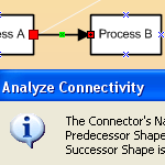
You have two Process Boxes in a Visio Diagram. They are glued together with a Dynamic Connector. You can easily see that they are glued together because if you select the Dynamic Connector, the wee red glue indicators are displayed. Red equals glued, green equals not glued. Simple enough, right? Well… yes… but…
Of Glue Types, Begins, Ends & Arrows
How do you tell which SmartShape is the predecessor and which is the successor? The Begin-Point of a Dynamic Connector SmartShape symbol displays as a miniscule “X”, and the End-Point displays as a miniscule “+”, but ONLY if you are using Point-to-Point Glue! If you are using Dynamic, or Shape-to-Shape glue, the glue indicators are slightly larger Red boxes with neither an “X” nor a “+” to assist you.

handles for point-to-point glue
 handles for dynamic glue

handles for dynamic (left) and point-to-point (right) glue
The arrow showing at one end or the other is of no help at all, since the user can change the arrows on either end at will, and in many diagram types there is no arrow at all by default.
Explore With Code Behind
So…
Enter a bit of code that comes to the rescue! Every Visio SmartShape symbol has a “Connects” Collection as part of its Object Properties. This collection can be queried to find out who is glued to whom, and in what order. The attached Visio diagramme has some verbosely documented code in the VBA environment which details how to find out which shapes are glued to which shapes and in what order: the predecessors and successors. To enter the VBA environment, simply press the Alt+F11 keys at the same time. You can then easily view the well documented code.
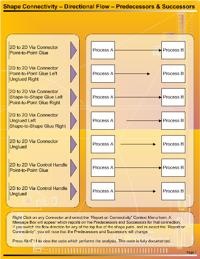
To use this diagramme, Right-Click on any of the Dynamic Connectors that you see in the diagramme, and select the “Report on Connectivity” context menu option. A Message Box will appear reporting on the connectivity between the SmartShape symbols. There are instructions at the bottom of the diagram to assist as well.

The diagramme illustrates seven different connection scenarios. Right-click each connector to get information about the connection.
I hope that this diagramme and associated code assist you in understanding how this analysis works and helps you in creating your own process flow diagrammes and analyzing their connectivity.
Download “Analyze Visio Connectivity VBA Code Sample”
s!Aj0wJuswNyXlhVHowTGr-1WTuRvN – Downloaded 6831 times – 103.00 BThanks David! Now for some related information…
Related Information
This download contains VBA code. You’ll need to allow the VBA macros inside of the document permission to run. If you’re not familiar with VBA macros, and the related security issues, please have a look at VBA Macro Security first. Once you’ve downloaded the file, opened the document, checked the code, and enabled the macro code to run, you’ll be ready to rock-n-roll!
Al Edlund also covers connectivity issues and offers VBA code to help in the analysis in: Path Analysis in Visio, by Al Edlund. Check it out!
This article has some simple code for automatically connecting shapes to each other: Connect All Shapes to Each Other.
And this document talks about a hidden, but sophisticated capability of Visio connection points, and offers some tools to help with the configuration: Connection Point Directions & Types.

A belated thanks for this David. Earlier today I devised a technique for doing the same thing by using the HitTest method:
Set shpAtEnd = cnx(1).ToSheet
' use HitTest to determine whether Begin end of connector
' is outside shpAtEnd
x = shpAtEnd.HitTest(shpTaskLink.Cells("BeginX"), _
    shpTaskLink.Cells("BeginY"), 0.01)

If x = visHitOutside Then
    ' do stuff
Else
    ' do other stuff
End If
Then I had a vague recollection of seeing something about this here and
is much cleaner!
Is any code available for connector analysis that would provide the predecessor and successor objects for all connectors on a diagram? I need to report on all connectors and their connected objects on a diagram.
Analyze Connectivity Between Process Flows
Submitted by Visio Guy on April 22, 2009 – 6:45 am
I’ve only written a few modules for excel spreadsheets, so I am a beginner.
Thanks,
hahnc