
If you use Visio for CAD-like purposes, you might need to make revisions or “AS-BUILT” modifications to your drawings from time to time. Often this is shown by drawing a squiggly cloud, or bubble, around the portion of the drawing that has been modified.
I’ve created three shapes for doing this for you to download.
The Way It Was
Visio has a Revision Cloud shape on the Annotations stencil that is…well…less than adequate. (You can find it under File > Shapes > Visio Extras > Annotations.) The problem is that you don’t get more bubbles as you stretch the shape; it just looks wrong.
Better Mousetrap
The shapes that accompany this post utilize custom patterns. Custom patterns are elemental graphics that can repeat themselves as line or fill patterns. I won’t go into how to create custom patterns in this article, but there are several links at the end of the post that will take you to this knowledge.
The new bubble shapes define a pattern that has three bumps. When you apply them to a shape, they simply repeat around the perimeter, giving you a nifty Revision Bubble!

You can see where the custom bubble patterns are stored in the Visio document by clicking this menu item: View > Drawing Explorer Window, then expanding Line Patterns tree node.
For this post’s download, you will see three patterns: RevBubble (L), RevBubble (M), and RevBubble (S):

To apply a pattern to a shape, simply select the shape and choose Format > Line from the menu. Click the Pattern drop-down and scroll all the way to the bottom to see the custom patterns available:

It’s also a good idea to apply some corner rounding if your revision shapes have a lot of sharp corners. The custom bubble pattern looks better when it goes around soft, rounded corners than when it has to be stretched around a sharp corner.
Make the Bubbles Bigger or Smaller
There are two ways that you can increase the size of the bubbles on your shapes.
1. Apply a different bubble pattern, ie: “RevBubble (S)” for small, “RevBubble (M)” for medium, and RevBubble (L) for large.
2. Increase the line-weight of the shape. The bubbles will get bigger when you increase the line-weight of the shape, but the thickness of the bubble-lines will also increase.
Of course you can mix the two, and this two-axis diagram attempts to illustrate what is going on! It’s kind of luck a Bang for the Buck chart, in that the bubble size increases as you go right or up — as you increase the pattern size or the line-weight.

Hope you find these shapes useful!
Download “Visio Bubble Revision Shape”
s!Aj0wJuswNyXlhx2GzEBgoFsQiRGE – Downloaded 20181 times – 103.00 BNeed More? Have Spare Change but No Patience?
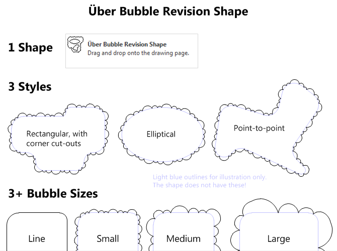
Try out the Über Bubble Revision Shape that I have developed, available via Gumroad. It has the same three bubble sizes as the free version above, plus a line mode that makes it easy to see what you’re doing, during adjustment. It also has three built-in forms: rectangle with corner cut-outs, ellipse, and point-to-point with eight independent vertices. This is all built into one single shape, so the shape is not only more capable than the free version, it is more streamlined! Have a look:
More on Visio and CAD
More Information on Creating Custom Visio Pattern
- Stupid Visio Tricks #821: Thought Balloons
Essentially the article I didn’t have to write! Unfortunately, I didn’t find this link till it was too late! This is from Dan Brown, the man who brought you the Visio Keyboard Shortcut Mousepad! - Creating Custom Line, Fill and Line-end Patterns in Visio
A farily-detailed article from Chapter 10 of the on-line version of Developing Visio Solutions on MSDN. - About custom fill, line, and line-end patterns
A rough overview of Visio’s custom line and fill patterns from Office Online. - How to create a custom fill pattern by using a bitmap image in Visio
An interesting step-by-step from Microsoft Support that shows that you can use images in your Visio custom patterns as well! - Custom line ends
A quick step-by-step process for creating custom line ends from Visio The Blog - Custom Visio Solution: Candy Equipment Manufacturing Example (VBA and Active X)
I wrote this demo for Visio Corp. back in 1999. There’s heavy use of custom patterns in the Visio document that you might find interesting! - Visio & AutoCAD

Hi Sargon,
Thanks for testing this. I had a feeling it might not work. One not-so-nice workaround is this:
1. Copy a bubble revision shape
2. Paste Special – as enhanced metafile
3. Ungroup
You will have a bunch of individual arcs, and individual text blocks for each line, and each change in text formatting. This mess can be grouped together into a single shape, which should export to CAD. But now you’ve lost the nice SmartShape behavior – so it should only be done after the shape has been adjusted to its end state.
I will report this to Microsoft as an issue.
Thank you for this response, however we convert in Batch, sometimes upwards of 1000 files. So this will not be an effective method to transfer the bubbles one by one.
These shapes are great, and make working in Visio much easier. Is there a way to get the same bubble revision shapes in Excel?
Hi Andrew,
You could always copy, then paste-as-metafile into Excel, and it *might* work. But you won’t have the nice resizing smarts that you have in Visio.
I wonder how hard it is to make custom shapes in Excel that have the little control handles. I can see this being pretty cool in Excel, as you implied!
How can I fill it with hatch to show demolition?
Hi Mohammad,
This version doesn’t accept fills, due to limitations of Visio and the mechanism I’m using to create it.
I have a prototype that allows fills, but it is more complicated, and uses VBA code. I haven’t had sufficient free time to publish it, unfortunately.
To add to previous requirement, it would be great if the bubble rev convert to AutoCAD. Currently is does not do that.
Thanks for this, I think I’ve been visiting the page to set this up everytime I start a new job for almost 15 years now… but question: how do I make it permanent so I don’t have to do this for every drawing?
Hi GG,
Not sure what you are asking. How do you make what permanent?
Is this something that can be added to Visio once and used across any document it opens or do you need to add the pattern to each document you want to use it in?
I frequently need to revise drawings made by other people.
For some reason my cloud line is inside out! Instead of being bubbly towards the outside, it is bubbly towards the inside of the shape, so it looks spikey! Help pleaseee
Hi Laura,
I just did a quick check. I assume you are applying a bubble pattern to a shape that you drew yourself?
If so, the shapes need to be drawn COUNTERCLOCKWISE so that the bubbles are on the outside.
I’m not sure why I built the pattern that way, as clockwise might have been more intuitive.
Cheers,
Chris