Need to arrange shapes in a circular pattern? This shape might help!
Update 2021.07.17: a third version of this shape has been published. See Visio Radial Grid v3. This article, as well as the version 2 article are still important for understanding how to use the shape, however!
Update 2018.10.05: a new version of this shape has been published. See Visio Radial Grid v2. This article still serves as the “base help file”, though, so have a quick scan below if you’re interested in the features of the shape!
As you may have discovered, Visio doesn’t have a feature for arranging shapes in radial patterns. Yes, there is a circular layout option for connected diagrams, but it doesn’t really space shapes evenly, and at equal radii. But we love circles because they are cool, and sometimes arranging shapes circularly can really help illustrate your point. So what can we do?
If you’re good at scripting, it’s not hard to write a small program to do this via automation. But there are a lot of fine points to consider, so creating a complete solution can become a much larger project. Who has time for that?
For many situations, just having a visual grid is good enough. While it is hard to “eyeball” shapes into a circular pattern, having a radial grid can make it easy enough to get to “good enough”.
Free Visio Radial Grid SmartShape
So I’ve been fiddling with that concept for a few hours, and have come up with a configurable Visio SmartShape that should help you to arrange things in a circle. You can download it from the link at the end of the article, and I’ll present the “help file” in the paragraphs below.
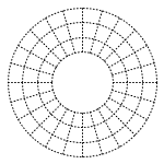
Basic Anatomy
The concept is simple. Let the user resize a circle as needed, and choose the number of rings and sectors. Here we can see an example in action, with radial lines, rings, text information, and slider “gauges” visible:
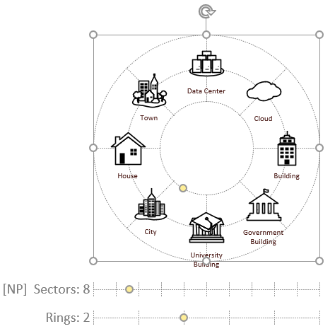
People doing network diagrams just love this kind of layout!
In the example above, the icons have been manually placed along the grid lines. While not exact, eyeballing an even distribution around just a simple circle would be difficult. With the grid shape, it is easier and more accurate. For fine-tuning, you can use the arrow keys to nudge selected shapes into position. (Pro tip: use Shift + ArrowKey for even finer nudging!)
Once you’ve arranged your shapes, turn off the grid and check your work! You can right-click the shape and choose Hide All to turn all the visuals off. This helps you get a feeling as to how well you’ve aligned your shapes:
 That little circle icon in the top-left corner is actually a UI element. It presents the shape’s context menu items, allowing you to turn lines and text back on, so you can see the grid! Without this, it would be difficult to select the invisible shape. It won’t print, show up in full-screen mode, or export to images or pdfs. It’s only there to help you turn the grid back on!
Ring and Sector Options
The shape can be configured to quite a few permutations. You can have 0-5 rings, and 0-50 sectors:
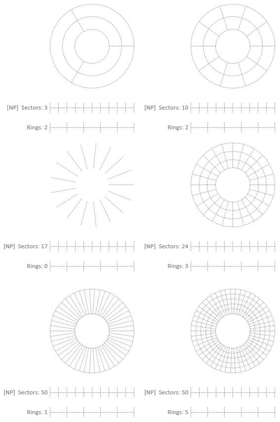
There are control handles to help you set the inner radius, as well as specify the number of sectors and rings. The control handles at the bottom work as sliders, and snap to integral positions. If you have a hard time hitting just the number you want, zoom in a bit, and the mousing will get more accurate:
Context Menu Options: Showing and Hiding Stuff
Right-clicking the shape will bring up the context menu, which contains a bunch of other options. These are concerned with turning various bits and pieces on or off, as well as setting the non-printing flag.
Once you know how to use the shape, you can turn off the text and scales to minimize distraction. In fact, you can turn just about everything off, individually! Or just use Hide All and be done with it! All the options are just a right-click away:

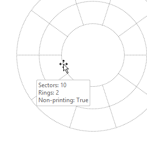
If you’ve hidden the text, and maybe the scales too, you can still get the counts by pausing the mouse over the shape. The tooltip will give you your sector count, ring count and non-printing status:
 By default, the shape is set to be non-printing. You’ll notice the [NP] text, if you are showing the information. If you turn off non-printing, the [NP] will go away, and the shape will print and export. The formatting isn’t locked in any way, so you can change the line color and pattern, along with the text formatting.
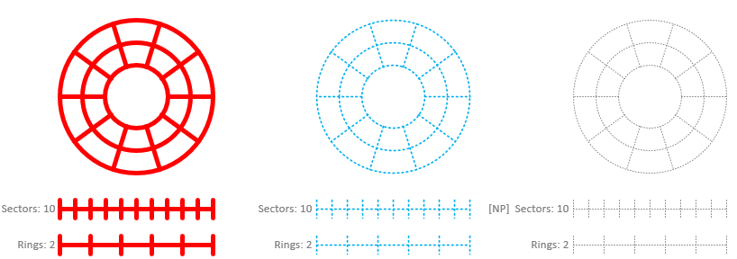
But as soon as you switch non-printing on, the internal smarts will blast the formatting, so that the shape looks like a guide: mainly gray dashed lines. This is to help suggest that this grid is a tool to help your position shapes, and won’t print.
Here we can see that I’ve given the first two grids pretty colors, but when I switch NP back on, it reverts to the gray look automatically:
click to view larger image
Connection Points
The shape contains one ring of connection points that can be used to actually glue shapes to the grid. The shape below has 39 sectors. If you have the Connection Point tool selected and View > Visual Aids > Connection Points checked, then you will see that them distributed around the second-outermost circle.
This shape has 39 connection points at the sector/ring intersections. The extra connection points fly into the center, for safe keeping:

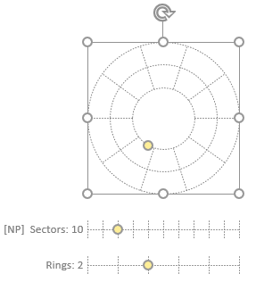
When using the grid for a single ring of shapes, I find that setting the shape to have 2 rings makes the most visual sense. You then try and hit the middle ring at the intersections with the radial lines.
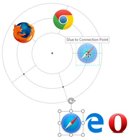
If you are gluing shapes to the connection points, this setup also works well:
 If you’re thinking; “Wuh wait, wait, wait, how do you glue shapes to connection points?”, you’re not crazy. There’s a little known feature that lets you glue regular shapes (as opposed to lines and connectors) to connection points.
Follow the steps below to make a “glue-to-able” connection point on any shape.
If the shape doesn’t already have a connection point, let’s add one:
- Make sure connection points are visible, via View > Visual Aids > Connection Points.
- Get the connection point tool, under Home > Tools > Connection Point (…look for the “X” icon).
- Select a shape that needs a “glue-to-able” connection point.
- Hold down the [Ctrl] key, then left click on the shape (usually right in the middle).
You should see a new magenta connection point on the shape, where you clicked.
Now we need to change the type of connection point
- Make sure you (still) have the Connection Point tool selected (see last set of steps).
- Right-click on an existing connection point.
A pop-up menu with three choices should appear. - Set the connection point to be Outward or Inward & Outward.
This will allow the whole shape to be glued to other “normal” connection points.

If you’re curious about these odd-sounding options, here are some notes.
- Most connection points are the default type, which is Inward.
- Outward points glue shapes to Inward points
- Outward points glue shapes to Inward & Outward points
- Inward & Outward points glue shapes to Inward & Outward points
An easier to understand naming system might be:
- Inward = Female
- Outward = Male
- Inward & Outward = Goes both ways
I believe this naming system was trademarked or copyrighted or patented at some point, so the Visio team had to come up with other names.
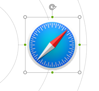
If you’ve glued a whole shape to a connection point, then Visio should give you some sort of visual feedback. This week, I am seeing green handles at 12, 3, 6 and 9 o’clock. But Microsoft seem to be changing the UI/handles frequently these days, so who knows what you’ll see:
Now when you move the grid, the glued shapes will follow. They will also follow along nicely if you change the grid’s parameters:
 Remember that extra connection points fly to the center, along with any shapes glued to them!

BUG: If you duplicate the grid + shapes glued to it, the duplication seems to break the glue (Visio 2016, Microsoft Visio Online Plan 2, Version 1809, Build 10827.20138 Click-to-run). I swear that this has functioned correctly in the past, but I can’t afford the time to investigate right now.
Regardless, if you’re working with the original version, having shapes glued to the points is pretty slick functionality!
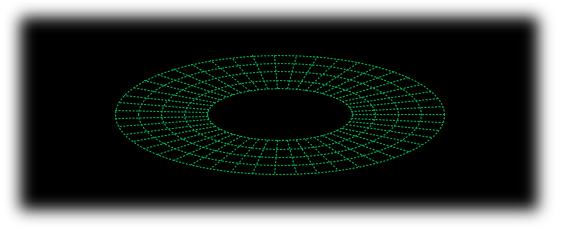
Elliptical Grids
I bothered to add a bit of extra math to the grid’s ShapeSheet, so that you could squash it into variously-proportioned ellipses, and it would still behave fairly well:

It looks pretty sweet if you’re going for the Battlezone look:
Note About a Visio Bug
There is a bug in Visio that makes this shape look “more broken than it really is.”
The problem: if you drag a master on to a page, then try to set the number of sectors using the control handle at the bottom, nothing happens! “What the…!?!?”
The simple fix: resize the whole shape. That seems to trigger recalculations in the shape, and everything works fine after that.
I haven’t come up with any hack to fix this in the shape itself, but you are likely to resize the shape anyway, and might not even encounter the problem.
Update 2018.10.09: the new version fixes the bug in the shape, so you don’t have to resize the shape to get it to work. The Visio bug still exists, unfortunately, but we’ve employed a workaround to get the shape to function properly!
Download
Update 2018.10.05: a new version of this shape has been published. See Visio Radial Grid v2.
You can download the Visio Radial Grid shape here:
Download “Radial Grid Shape”
s!Aj0wJuswNyXlhHvrvaIUmIOxYJO6 – Downloaded 4505 times – 103.00 BTODO
Here are some things that could be done to improve the shape further:
- Add feature to allow the zero-point to change. It is currently at 3 o’clock. (If the shape is circular, it is easy enough to just rotate it. But for ellipses, this won’t work.)
- Add feature to allow clockwise or counterclockwise progression of radial lines/connection points.
- Add option to turn the grid into an actual Visio container so that shapes can be added to the container, and move with it.

Download does not function. Impressed on what you accomplished with this.
Thanks, George! I missed one checkbox when setting up the download. It should work now!
other than the fact it doesn’t work, it looks pretty good
Working now! Looks amazing
Yup, the sector slider control has somehow gotten broken when I turned the shape into a master. The weird part is that it (obviously) worked just fine when I was creating all of the illustrations for this article, and all of the shapes work in the download-document. But when you drag the master out onto the page NOW, the sectors don’t work.
Investigating….hope to have a fix soon!
Ok, here’s one workaround: if you drag a new grid shape from the stencil onto a page, the sector handle won’t change the number of radial lines UNTIL you resize the shape. So just grab a corner handle and change the size of the shape to get it working for now. Visio appears to have some sort of bug–probably some overly aggressive optimization that made some bad assumptions.