 I’ve been working on a three-label, Visio dynamic connector and thought I’d share some of my design thoughts with you.
Visio’s main forte is helping users to create connected diagrams, be they flowcharts, org-charts, network diagrams, software diagrams, wiring diagrams and more. There are several articles on this website that talk about Visio connectors in one way or another.
Maybe you’ve read or seen some of these:
- Text Along a Connector’s Path in Microsoft Visio 2010
- Making Bends in Visio’s Dynamic Connector
- Analyze Connectivity Between Process Flows
- Sample Banking Scandal Visio Flowchart
Feedback from these articles, along with various work I’ve done for custom Visio schematic diagramming solutions, got me thinking about producing a three-label connector, which I will soon release into the wild for a modest fee. Look for it on the Products page soon.
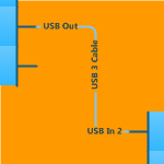
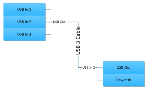
The goal is to enable users to label connectors something like this:
The text at one end of the connector reflects the terminal at the other end. This allows you to more easily read diagrams where connectors connect things that are far apart. I can see that terminal USB In 1 connects to USB Out without following the connector all the way to the other end. The middle text can then be used to add some extra information. Here we see that this should be a USB 3 cable.
I won’t go into how I actually built the connector to display three text blocks in this article. For you Visio-geeks out there, I’ll hint that ShapeSheet functions added in Visio 2010 make this much more do-able, although it wasn’t impossible in Visio 2007.
Instead, I’ll discuss the three methods I came up with for inputting the text.
One Delimited Text Block
When you’re editing the text in a Visio diagram, it can get a bit tedious to have to pick up the mouse, click on a shape, possibly enter text edit mode, then return to the keyboard to type. Doing that three times for each connector could get old.
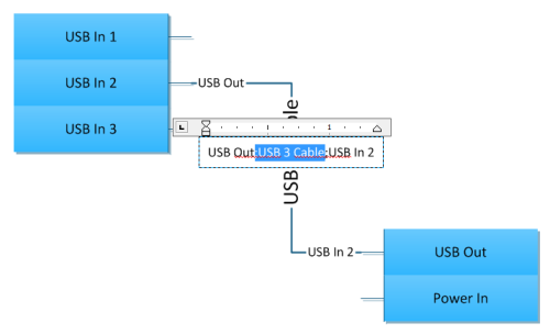
So this first flavor allows you to type one block of text that holds the information for all three bits. You tell the shape which part of the text goes where by separating the three items with a semicolon. Click the connector, then type: USB Out;USB 3 Cable;USB In 2, and you’re done!
The other major trick with this shape is that the main text block is actually hidden. You only see the text when you’re typing. Thereafter, the ShapeSheet takes over, splits the text into pieces, and sends those pieces to the subshapes at the beginning, middle and end of the connector.
 If you’ve read this blog, you have probably seen me use this technique before. Notable examples include:
- Automatic Chevron Process Shape
- Design Web Pages With This Visio Breadcrumbs Shape
- Run Circles Around Your Text With the Circle-text Title SmartShape
- Repeating Diamond Title Visio Shape
Shape Data Fields
The second iteration lets you set the text using three Shape Data fields. This also allows you to stay at the keyboard, since you can Tab between fields.
For the shape pictured below, you need only select the shape, then click on the Text Begin field in the Shape Data window.
As long as your left pinkie knows where the Tab key is, you won’t have to leave the keyboard to finish editing all three text blocks. Just type value-tab-value-tab-value-enter and you’re done! Again, the ShapeSheet is wired so that the each text block reads one of the values in the Shape Data.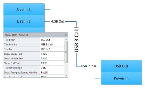
Subselection
The third method is the most direct, but gets us back to the original complaint: three sets of clicking-on-a-shape, then returning to the keyboard to type.
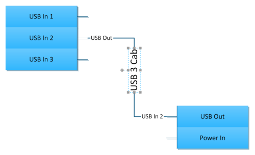
I would argue that this is the simplest method, in terms of explaining it to novice users. They only have to learn how to subselect shapes. Simply put, you subselect shapes in a group by first clicking the “top-level” group shape, pausing for half-a-second, then clicking again on the subshape. Here we can see the middle text block is subselected. Don’t worry about craning your nick, though! When we start typing, the text will be right-side-up while we type.
There is one glitch that can occur with this method: What happens when the user deletes all of the text? How do they subselect an empty or blank shape that could possibly be either very small, very invisible, or simply unselectable?
I’ve developed another technique for that. If a subshape has no text, the ShapeSheet detects this and makes the shape a minimum size, and shows a gray fill color. It also sets the subshape to non-printing, so that the ugly gray boxes don’t spoil an otherwise beautiful document when it is output to paper and delivered to customers.
The gray box gives the user a nice target to subselect, and they can happily resume editing connector text at a later time, when they’ve decided what to type.
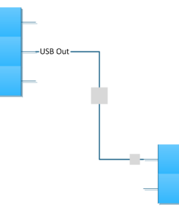 The connectors I’ve built also have the option to selectively show or hide each text block. So if one of the stations has no text, and you turn it off, the gray box goes away until you turn it on again.
Conclusion
Hopefully this gives budding shape designers food for thought. Or if you’re contemplating enhancing shapes or templates that you use in your business, this might also be interesting to you. I can’t really say if one method is better than the other. I think it depends on user experience levels and workflow for the particular discipline.
From my perspective, the ultimate goal is to create an integrated solution where an add-in or VBA macro watches the user draw. When the user creates a connection, the text block at the other end of the connector gets populated with information at the point of connection. There are many technical applications where folks create diagrams that need this type of automated user assistance.
Such a solution would save a lot of users a lot of typing! And any of the three structures would be quite usable by the code that could detect and read information about glued connectors. The three-label connector is the first piece of the puzzle.

Hello Chris,
nice shape and maybe a good business idea (looking at the many threads about this kind of connector in the forum).
One question popped up in my mind while reading the article: If one edits the (hidden) main text of the shape or the text of the subshapes: Is that propagated vice versa, and is it propagated to the shapedata?
I think some of the org chart shapes offer the possibility to alter ShapeData or the shapes text and they both keep the other method up to date but afaik that is handled by the Addon.
Hi Jumpy,
No, it’s one way. Subshapes take a piece of the hidden/main text.
The org chart shapes are being driven by the org chart (“OrgC11”) add-on that comes with Visio. That add-in is watching for changes to either shape data or text and doing some intelligent things to keep them in synch.
Generally Visio/ShapeSheet stuff only goes one way, although as you know, we try our best to do tricks!
I love this idea. I draw very large InterConnect Diagrams (ICD) all the time and this would help me. I’ll be in line to purchase.
Hi
This is really usefull, I have been searching for solution for a while
Niels
So where is the product? I am ready to buy…………….
Here, here! Ready to buy.
Ok guys, like my Dad would say, “I’ll get my butt in gear” and get them ready for prime-time!
Thanks! Please email me as soon as it is good to go. I can (seriously) start using it yesterday 🙂
Hi All,
The shapes are very close to complete, but I ran into one bug that I want to fix before release, and I’ve got a lot of project work to finish this week. Thanks for your support and patience!
Hi Chris,
Thanks for all the tutorials – I’m new to Visio ShapeSheets and without your resource I wouldn’t have gotten to the limited stage I have.
I appreciate you’re looking to make this a commercial product, but could you elaborate a little on what you’ve hinted at in the article – specifically, how do you approach adding additional text (and hopefully by extension, any “subshape”) to the dynamic connector?
I’ve been trying all day but just can’t get anything to work – I’ve tried grouping shapes but then I lose the features of the dynamic connector (unless I sub-select it from the group, which doesn’t seem right?).
Would you mind giving me a shove in the right direction?
So what’s the story morning glory? Still in works?
Let me know if I should fax over some Gatorade and midnight snacks!
You guys are awesome, thanks for your patience! I am juggling a bit of summer vacation with trying to get this done. If you know anything about the ShapeSheet, I currently have one “circular reference” that might be harmless, but I want to get it ironed out before I release this thing.
Cheers,
Chris
Hi,
thank you for tips and suggestions on Tripple tagged connectors.
I found an easy way if you have straight connectors.
1. In ShapeSheet : Change alignment for text…
TxtAngle=ANGLEALONGPATH(Geometry1.Path,1)
I like to add Text Block background (30% transparancy)
2. Open Format for Text->Tab and add 2 tabs.
3. Edit the tabs in ShapeSheet,
Tabs.1.posision=TxtWidth*0.5
Tabs.1.alignment=1 (center)
Tabs.2.posision=SQRT((EndX-BeginX)^2+(EndY-BeginY)^2)*0.75
Tabs.2.alignment=2 (left)
Now edit the text for connection.
Left text : Text at beginning of line
First tab : Center text
Second tab : End of line
Change space between object and text by editing factor (0.75) in Tabs.2.posision
BR,
Oyvind
This would be awesome if it could be combined with your oblique connector
Good idea, Tango!
Hi, were you ever able to finish this awesome connector?
Hi, I’ve also been very interested in this connector and ready to buy when available, thanks!
Could you give us an ETA when thisv awesome shape will be avaible?
Best!
Please can you advise if this is available?
Thanks,
C.
Is this ready for purchase yet?
Any news about when will it be ready to distribute.
Also the posiibility to use it for cabling diagrams in the form of having the same number ( entred by hnad ) on each side will be nice.
regards and happy new year
Still waiting with great anticipation is it ready yet?
Greg
Hi Gregory,
Thanks for the prodding, and I apologize for the ridiculous delay. I’ve been oversubscribed with project work since the beginning of the year. I did manage to spend a few hours on the thing last week, but there is still one bug I want to work out, and some stress-testing I want to do before I release it.
I’ve been following this for a while and look forward to see what you came up with. Curious though if there is an easy way to do something similar but instead of different data at each end the data is the same? For example a wire ID?
can you share file to us?
hi,
any chance for the connector yet?
Where is this connector for the love of god??
A MEN!!!
Hi,
I would like to buy it yesterday… any ETA.
thanks.
Any luck with this killer Visio Add-on?
The ability to pull text data from connected shapes, that than will be utilized to generate >ToFrom< Labels would be great.
Are we there yet?
Heh. Up at 1AM tonight trying to fix the circular reference in the ShapeSheet to get this thing ready. The shapes seems to work fine, but I don’t like this circular thing and want to eliminate it if possible.
Then I’d like to test performance.
Can you guys that are interested in this comment on how many connectors you would have in a typical drawing? Maximum connectors you might have on a drawing?
Thanks,
Chris
Hi Chris,
Between 100 and 1000 for us… 4-500 would be average
My drawings tend to average 10 to 250 connectors.
Usually between 1- 250
Hi Chris,
my drawings have hundreds of links.
Hello,
Also interested !!
When can we expect it?
Thanks a lot
Best Regards
Hello visguy
This is exactly what I am looking for! When would it be available for purchase ?
I might as well jump back in here too. Still following, still waiting for a connector like this! Hope to see it one day!
I’m still following too. I still want it. Willing to pay.
Yep me too ? everyday use!
Hi All, thanks for reiterating your interest! I’ve gotten so busy I’ve not been able to get to this. Part of the problem is that I was trying to make it too complicated, and therefore impossible to finish. I think I need to try and make “very useful” version and get it released!
Sorry for the ridiculous delays!
That would be awesome!
Hi Visio God, it’s been ~6 years now 🙁 I think at least some form of those connectors would be cool to have by now, especially if the label would come from a field of the connected Shape Data. I’ve tried everything, and had no luck. It’d even be cool if it’d just be a simple connector that has one label, and that one label would be auto-created by a single field in one end of the connected shape. My need is to connect servers and display the ports of the target (listening) device. As the ports can change from drawing to drawing, and the “data” of a ton of shapes gets automatically updated by a linked data source, this would save the extra manual step of also updating all the connectors.I’d pay for such a connector (within reason..)
Love the work you do, you’re been a great help over the last few weeks of my “journey into advanced Visio stuff ”
By the way, is MS sun-setting Visio? It just seems that it’s not getting much love, neither from MS (missing integration into Office 365, very basic Data Source config/options) nor from the technology writers .. there’s almost no documentation out there that goes beyond the basics/ “step by step” stuff…?
Cheers
Max
I’m still willing to pay for this. Is there any hope of it becoming a product?