 In our last article on smart frames, we built a SmartShape that maintained a constant border-thickness, no matter the size of the shape.
It was a fairly simple frame, it got the job done, but it had a uniform frame-thickness all the way around, and offered no way for an end-user to change that thickness.
In this article, we’ll add some flexibility to the shape by making separate margin parameters for each side. We’ll also expose the margin settings to the user via Shape Data fields.
Freedom for All Sides!
The best part about a smart frame is that the border stays the same when we resize the shape. But that doesn’t mean we want the border to be the same thickness all the way ‘round!
Monitors and displays are often thicker on the bottom. Racks have thin rails for sides, and thicker bits on top and at the bottom. One might start to think of drawing frames for title blocks and zones that allow more space on one side for hole-punches and binding. The list of examples is endless.
So lets free up our sides! The first step is to add three more User-defined Cells section, so that we can control the thickness of each side of the frame.
So whip out a copy of your shape from the first article, and open up the ShapeSheet. You can add user cells by:
- Placing your cursor in an existing User-defined cell
- Right-clicking
- Choosing Insert Row from the menu
Do this three times. Then rename the original cell, and give the new ones names. You should see something like this when you’re done:
| User-defined Cells | Value | Prompt |
| User.marginLeft | 5 in | “” |
| User.marginTop | 5 in | “” |
| User.marginRight | 5 in | “” |
| User.marginBott | 10 in | “” |
You can set the values to whatever you feel like. But only User.marginLeft will have any sway, because we haven’t linked the geometry to the new cells.
Re-smarten the Geometry
Geometry 2 represents our inner-frame, and it needs to be modified to take advantage of our new parameters. I could go on about the theory, but it’s probably easiest to just copy the new formulas shown in the ShapeSheet below.
Remember, if you get lost in the vertex-soup, you can always look for that black dot in the drawing window. It visually shows you which vertex is represented by the geometry cell in which your cursor is currently sitting!
| Geometry 2 | ||||
| Geometry2.NoFill | FALSE | Geometry2.NoLine | FALSE | |
| Geometry2.NoShow | FALSE | Geometry2.NoSnap | FALSE | |
| Name | X | Y | ||
| 1 | MoveTo | User.marginLeft | User.marginBott | |
| 2 | LineTo | Width-User.marginRight | User.marginBott | |
| 3 | LineTo | Geometry2.X2 | Height-User.marginTop | |
| 4 | LineTo | User.marginLeft | Geometry2.Y3 | |
| 5 | LineTo | Geometry2.X1 | Geometry2.X1 | |
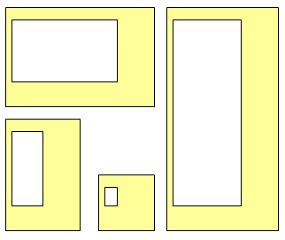
Now you can individually specify a value for each margin! Go ahead, enter some wacky values and take your new shape for a spin!

Above, you can see four different margin thicknesses. But the margins still maintain their sizes, no matter how we stretch the shape!
Link to Shape Data Fields
Now, let’s give our end-users access to the frame’s settings. And no, you Visio die-hards, Window > Show ShapeSheet is not an end-user feature!
We’re going to expose the user-cells to the world by linking them to Shape Data fields (Custom Properties for Visio-2003-and-earlier users)
Now, Visio has a nice user-interface for adding Shape Data fields, but since we’re already in the ShapeSheet, we’ll do it the programmer way:
- Right-click somewhere in your ShapeSheet Window
- Choose: Insert Section…
- Check Shape Data
You’re done! You should have a shiny new Shape Data section, with one row in it:
| Shape Data | Label | Type | Value |
| Prop.Row_1 | “” | 0 | 0 |
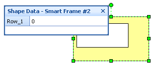
Not extremely useful or interesting, except that if you go back to the drawing window and select your shape, you’ll notice that the Shape Data window displays your brand-new field! (Note: you might have to turn the window on via: View > Shape Data Window)
Now the obvious thing to do would be to add three more rows of Shape Data and link each one of them to the corresponding User-cell. But let’s not be so obvious!
You see, the neat thing about having both the User-defined cells and the Shape Data fields is that we can choose what to expose to the user.
I mentioned earlier the case of monitors and displays. They usually have equal thicknesses for the left, top, and right sides, but the bottom is thicker—it adds a stabilizing visual weight to the aesthetic.
So lets just add two Shape Data fields. One for the margins on the left, top and right, and another for the bottom. I’ll let you figure out how to get your Shape Data section to look like this:
| Shape Data | Label | Type | Value |
| Prop.MarginLTR | Left, top, right margin | 2 | 5 in |
| Prop.MarginBottom | Bottom margin | 2 | 5 in |
The Label cell is what the user sees in the Shape Data window. You can add some pretty text so that the user doesn’t have to read MarginLTR and get scared.
Type = 2 tells Visio that this field should hold a number (or a value-unit pair.) If the user enters “Bob” in the Shape Data window, Visio will complain that Bob is not a number. But 2in, 3mm, 4miles, etc. will be perfectly fine.
Re-smarten the User-cells
Now your geometry cells are just as smart as they were before we added the Shape Data. But the User-cells are now the weak-link. They still don’t know diddly about the user-interface, and the new parameters we just added.
Soooooo hook ‘em up, cowboy!
| User-defined Cells | Value | Prompt |
| User.marginLeft | Prop.MarginLTR | “” |
| User.marginTop | Prop.MarginLTR | “” |
| User.marginRight | Prop.MarginLTR | “” |
| User.marginBott | Prop.MarginBott | “” |
By the way, you create cell-reference formulas just like you do in Excel:
- Put your cursor in User.marginLeft
- Type “=” (cell waits for more info)
- Click on the Value cell in Prop.MarginLTR
- Hit Enter
Sounds familiar, eh?
You can download a Visio drawing containing this version of the smart frame and and check your own version against it:
Download “How to Make Smart Frames and Bezels #2”
s!Aj0wJuswNyXlhVXo4gF0rQ7tQqeG – Downloaded 2883 times – 103.00 BNext…
In the next article on Smart Frames and Bezels, we’ll add a way for users to directly manipulate the frame borders using control handles, so stay tuned!
Previous…
Be sure and read our previous articles on How to Build Smart Frames and Bezels:


Leave a Reply