 If you create elevation drawings for rack systems, for cabinetry, for A/V systems with TVs and video monitors, or for walls with doors and windows, you’ll find yourself needing frame shapes.
And while your equipment may come in different sizes, the frames should maintain consistency when they are stretched.
For example, you may have several sizes of monitor: 19-inch, 21-inch, 48-inch, etc. Even though the picture gets bigger, the bezel around the display stays the same thickness. You get more display area, not more plastic!
A Visio SmartShape offers an elegant way to depict these objects. With a little bit of ShapeSheet programming, you can make one shape that can do the job of several!
We’ll call these shapes Smart Frames. This article is the first installment in a series about creating and understanding Smart Frame shapes in Visio! So enjoy this article and stay tuned in the future!
Dumb in Proportion
You can’t get a Smart Frame by just drawing. You’ve got to dig a little deeper. You see, when you draw shapes and vertices, Visio gives each vertex a proportional location. So if you stretch the shape, these proportions are of course maintained.
But we want to create a shape that has parts that maintain fixed sizes, so proportionality is the wrong tack for us.
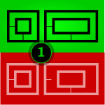
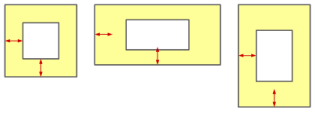
If we create a frame by drawing two rectangles and combining them, or grouping them, or if we import some clip-art rendition of a frame, we’ll be sorely disappointed when we resize it:

The red arrows show what we want. The yellow frames show what we get. See how the shape stretches and squishes? Every time we needed a new size of equipment, we would have to re-edit the inner vertices. Not very practical, especially when you are trying to deliver drag-and-drop solutions to your users!
So proportional resizing works for the outer rectangle, but not for the inner rectangle. We need a mixture of proportional resizing and fixed resizing to make a frame work properly.
Smart in Fixed Ways
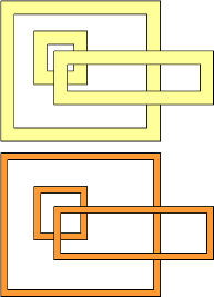
The behavior we are looking for looks more like this:
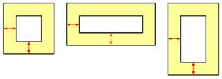
In this shape, the inner rectangle maintains a constant offset from the outer edges. The vertices are located at fixed distances from the left, top, right and bottom of the shape.
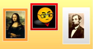
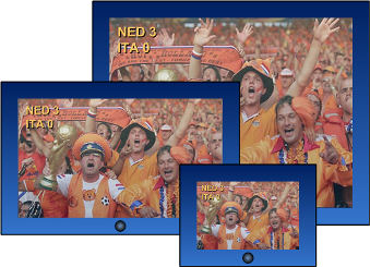
With just one frame, we can build a whole line of monitors of various sizes. Like this!

Now, I suppose that the real-world bezels of video monitors change somewhat with the size of the equipment, but not that much. I find the consistency makes a diagram appear more orderly, and it is easier to look at.
Also notice, no matter how big or small the monitor, Italy still got their butts kicked.
Let’s Draw!
Well, the prospect of replacing 57 different monitor shapes with just ONE looks pretty cool, doesn’t it?
So let’s get going and build our first simple Smart Frame. It will involve some ShapeSheet programming, but it’s not too hard.
Make a Scaled Page
Since most elevation drawings are done to-scale, let’s start with a scaled drawing. You can just open one of Visio’s Floor Plan, Home Plan or Office Layout templates, or start with a blank drawing.
To create a scaled drawing from scratch:
- Click the New toolbar button or File > New > New Drawing menu item
- Go to the: File > Page Setup dialog
- Select the Drawing Scale tab
- Click: Pre-defined scale
- Select Architectural, 1/2″ = 1′ 0″ or Metric, 1:25, depending on your US-idness
Rough-out the Frame
Now we just need to draw two rectangles that will become our frame. You can draw one inside the other, but don’t worry too much about precision. We will set the exact (x, y) values for each vertex using Visio ShapeSheet formulas later.
To make things easier, we’re going to Combine the rectangles together into a single shape. This is slightly different than grouping. But it will make it easier to work on the vertices in the ShapeSheet.
But enough talking. I command you to do this, now:
- Select the Rectangle Tool from the Drawing Toolbar
- Draw two rectangles on the page, one inside of the other
- Switch back to the Pointer Tool (Ctrl+1)
- Select both rectangles
- Combine them using Shape > Operations Combine
- Choose: Window > Show ShapeSheet from the menu
You should now see a frightening interface that looks like Excel on drugs.
Bonus Trick: for those of you who enjoy keyboard shortcuts and undocumented Windows calls, you can skip the whole Combine procedure by doing this: 1. Draw the first rectangle 2. Hold down Ctrl + Shift, and draw the second rectangle inside of the first. Visio will combine the rectangles as you draw!
Let’s Program!
Welcome to the ShapeSheet: the thumping organism behind every Visio shape. It’s an Excel-like interface that defines the various properties of a shape, and gives each Visio shape the potential to be much, much more than just dumb clip-art.
Like Excel, the ShapeSheet can hold not just numbers, but formulas and expressions that breath intellect into SmartShapes.
If you’ve never seen the ShapeSheet before, and are getting a bit nervous, I suggest you get properly introduced by reading: John Goldsmith’s visLog: Just for starters. For those of you still reading, we need to add smarts to the geometry. After all, we’re building a Smart Frame!
ShapeSheet Sections
Amongst all of the sections that you see in the ShapeSheet window, take special note of Shape Transform, Geometry 1 and Geometry 2. Shape Transform defines the overall size of the shape (per the Width and Height cells), while the two Geometry sections define the rectangles that we just combined together.
Values and Formulas
The cells in the ShapeSheet can display either values, or formulas. For this exercise, we’re interested in the formulas, so make sure they are showing. To do this, just Right-click anywhere in the ShapeSheet window and check Formulas, not Values.
You should now see lots of formulas that look like “Width*0”, “Width*0.2538”, “Height*0”, etc. Once you understand that the point (0, 0) is the lower-left corner of the shape, and the point (Width, Height) is the upper right corner, it all starts to make more sense.
Outer Rectangle
We’ll set Geometry 1 to be the outer rectangle. The formulas for the vertices simply follow the edge of the shape, and are easier to understand, so it’s a good place to start.
You might see existing formulas like: “Width*0”, but you can enter 0 just as well, the end result is the same. Similarly, “Height*1” is the same as “Height”.
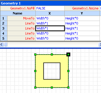
So first, make your Geometry 1 formulas look something like this:
| Geometry 1 | ||||
| Geometry1.NoFill | FALSE | Geometry1.NoLine | FALSE | |
| Geometry1.NoShow | FALSE | Geometry1.NoSnap | FALSE | |
| Name | X | Y | ||
| 1 | MoveTo | 0 | 0 | |
| 2 | LineTo | Width | 0 | |
| 3 | LineTo | Width | Height | |
| 4 | LineTo | 0 | Height | |
| 5 | LineTo | Geometry1.X1 | Geometry1.X1 | |
Fairly simple formulas that define the outer edge of the shape.
Some Visual Help
Note, when the cursor is in a Geometry cell, you can see a black dot at the corresponding vertex in the shape on the screen:
Frame Thickness Parameter
Now we need to add a parameter to the shape to control the frame thickness. A good place to store a parameter is in a User-defined cell.
User-defined cells are similar to Shape Data fields (formerly Custom Properties), except that they are hidden from the end-user. Only developers will see them.
To add a User-defined cell:
- Right-click anywhere in the ShapeSheet window
- Select: Insert Section…
- Check: User-defined cells, then hit OK
You’ll notice a new section appears in the ShapeSheet - Select the cell with the red text that says: User.Row_1
- Rename the User row to User.margin by typing “margin”
- Enter a value for the thickness of your frame, say 5 in or 12 mm. You can play with the value later to see what happens.
You should see something like this:
| User-defined Cells | Value | Prompt |
| User.margin | 5in | “” |
The vertices in Geometry 2 can now follow User.Margin, instead of being individually coded. We can parameterize our shape, so that one change to User.Margin will affect many vertices!
Inner Rectangle
Now that we have a variable for the frame-thickness, we can program the inner rectangle’s vertices. So down to the Geometry 2 section we go.
Since the edges of this rectangle need to be a fixed distance from the edges of Geometry 1, we’ll refer to User.Margin quite often!
Make your Geometry 2 section look like this:
| Geometry 2 | ||||
| Geometry2.NoFill | FALSE | Geometry2.NoLine | FALSE | |
| Geometry2.NoShow | FALSE | Geometry2.NoSnap | FALSE | |
| Name | X | Y | ||
| 1 | MoveTo | User.margin | User.margin | |
| 2 | LineTo | Width-User.margin | User.margin | |
| 3 | LineTo | Geometry2.X2 | Height-User.margin | |
| 4 | LineTo | User.margin | Geometry2.Y3 | |
| 5 | LineTo | Geometry2.X1 | Geometry2.X1 | |
Once you’ve completed entering the formulas, your frame should behave properly. No matter how you resize your shape, the border thickness remains constant.
Hopefully the formulas make sense to you. Points on the left side just refer to User.margin–they are that far from the left edge. Points on the right are User.margin from the right side, or Width – User.margin.
Formula References
To save repeated calculations, some cells refer other cells in the section. For instance, the last row represents a point that is the same as the first point. So both x- and y formulas refer back to the first row.
You can enter formulas the reference other cells just like in Excel:
- Place your cursor in a cell
- Type “=”
- Click on another cell
- Press “Enter”.
You can change the value of User.margin, but the shape will continue to react correctly:

Mission Complete!
So now you have created a Smart Frame! I hope you find this marginally cool, and I hope that you come up with lots of neat applications for your new SmartShape.
While you are playing around with your new creation, you might try the following:
- Group your frame together with an imported image to make a video monitor
- Set User.margin to a negative value and see what happens!
- Create a Shape Data field called Prop.Margin and try to hook User.margin to it. Now you can change the margin from the User Interface…
Next…
…which is just what we’ll be doing in the next installment of Smart Frames. In that article, we’ll expose margin settings to the end-user via a variety of methods, and we’ll make our margin more flexible by creating settings for each side. You can read it here:

please
provide me right way because i dont have latest version and it is needful, how can i insert rounded rectangle to my sps/xsl using altova, please provide me step by step, if is it posibble then using example
thanks
Hi gopal,
I’m not sure exactly what you are asking.
If you want a “smart frame” with rounded corners, then you will have to figure out the necessary geometry to do that. The example and explanations in this article should give you a good start on how to do that.
In a shape’s geometry section, you can insert rows call “ArcTo”. You will need four of these around the edges of your rectangle. The ArcTo row has a third parameter after x and y. This is called the “bow”.
For right-angles, the bow of a circular arc is r*(1-cos(ang/2)), which ends up being r*0.29289 for 90-degree bends. “r” is the radius of the curvature for your corner. “ang” is the angle for a corner, which is 90 degrees for square stuff.
Good luck!
visio 2013. this is exactly what i need. Entered it 5 times no mistakes but it doesn’t work. I end up with one huge box that doesn’t scale.