ECB asked in a recent newsgroup post:
“How can I make a 45° corner that maintains 45° when the shape resizes?”
Such a shape would be useful, for say, creating a “Document” shape. It’s also the type of thing that the CAD-oriented folks might like to create, only they would call it a “chamfer”.
In this article, we’ll show you how to create such a shape with Visio’s drawing tools, and to add the special behavior using Visio’s ShapeSheet interface.
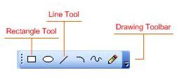
First we’ll create some rough shapes. Make sure that the Drawing toolbar is visible in Visio’s toolbar. Just right-click in a blank area of the toolbar and you’ll see it in the list.

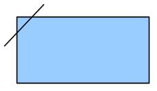
Using the rectangle and line tools, draw a rectangle and a cutting line as shown below. We’ll use the line to slice off the corner of the rectangle.

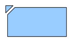
Once you have the shapes drawn, select them both, then choose Shape > Operations > Fragment from the menu. This will give you two separate shapes:

Now it’s time to add some intelligence to the corner. If you stretch the shape right now, the corner will stretch along with the shape, which is not what we want. We want the corner to maintain it’s aspect ratio – to maintain it’s proportions regardless of how the shape is stretched.
To add the smarts, we need to use the ShapeSheet. Select the shape and choose Window > Show ShapeSheet. You’ll see an Excel-like looking interface that governs the behavior of the geometry, text, formatting, and data of the shape.
First, we’ll add a paramter to the shape, to store the size of the corner, and to allow users to change the corner-size via the Custom Properties user interface. From the ShapeSheet menu, choose Insert > Section and check Custom properties.

You’ll see the Custom Properties section appear in the ShapeSheet. You can rename the cell in the left-most box to “chamfer”, and add a nice Label, which is what users will see in the Custom Properties dialog box. Finally, set the Value cell to 0.25 in, or something similar.
When a user selects the shape and has the Custom Properties window visible — either via View > Custom Properties Window or Shape > Custom Properties — he will be able to change this property directly in the window, without a need to go to the ShapeSheet.
Now that we’ve create a parameter, it’s time to hook it up to the geometry! If you scroll down a bit, you’ll find the Geometry 1 section. This section contains 6 rows that represent the x-y coordinates of each point on the shape. The shape has five points, but six rows, because the last row returns to the first row to close off the shape.
The origin, or starting point is the lower-left corner, so you’ll note that a point that is located at (0, 0) will have formulas of (Width*0, Height*0) in our geometry section. The top-right of the shape is then at (Width*1, Height*1). Not so difficult, eh?
By default, all of the points have proportional formulas, ie: “Width or Height times something.” But we want our corner to always be 0.25 in from the left/top of the shape. Or if we start to talk ShapeSheet, our corner is “Prop.chamfer from the left and from the top of the shape.”
If you have a look at the finished geometry section below, the yellow-highlighted cells show the formulas for making this happen:
The key cells are Geometry1.Y1 and Geometry1.X5:
Geometry1.Y1 = Height – Prop.chamfer
Geometry1.X5 = Prop.chamfer
Notice how Prop.chamfer refers to our Custom Property. It allows us to parameterize the shape so that we can quickly make changes by editing a single value.
You might also need to set the formulas in the last row to refer back to the first rows, and officially close the shape. To do this, simply select a cell, type “=”, select an X- or Y-cell in row 1, and hit Enter. Just like you would in Excel!
Another note: it’s possible that the order of the points in your shape might be different than those in this tutorial. If that’s the case, you’ll have to find the correct corner points yourself. But never fear! When you select a cell in the ShapeSheet, Visio highlights the corresponding vertex in the drawing window, on the shape, so you can see which formulas correspond to which points!


Thank you for a simple description of a really powerful addition to Visio. Keep me out of trouble for days.
Hi Chris,
Just to point out that in the ShapeSheet menu, in my Visio 2007 version, “Custom properties” appears to be “Shape Data”
So I had to check
“Insert > Section and check Shape Data.
Just a detail
Thanks for this article.
Hi Chris,
I would like to get a modified “right angle” “dynamic connector” where each corner is chamfered @ 45 degrees at a fixed (or control handle controlled) length.
To get an idea of what I’m looking for, use a built-in “dynamic connector” symbol and connect 2 shapes where there is one or more 90-degree corners on the connector itself. Then change the corner rounding to something non-square.
The connector I’m looking for would look a lot like this, but instead of a rounded corner, it would have a chamfered corner.
Is this doable?
Thanks!