
Today I saw a question in the Microsoft Visio newsgroups.
Stefan wanted to know how to make a 3D arrow look like it was going through a rectangular plane.
Of course I couldn’t resist the opportunity to do some drawing, plus it seemed like a nice topic for today’s Visio 3D drawing tutorial!
If you’ve perused the Visio Art page, you might have seen this Pin and PinLoc illustration:
or perhaps the Knife Through Iron Chef piccie:

Both of these visuals have elements of what Stefan needs.
So it’s possible to do this with Visio, but how?
Fake Isometrics
I like to draw using Visio’s grid, which you can turn on via the View > Grid menu. Armed with the grid, some settings under Tools > Snap & Glue, and the Line tool, you can do a good job of drawing consistent “isometric” shapes, as long as they are fairly simple.
Here I’m creating the first part of our 3D illo: the square, or plane through which the arrow will pass. I am using “isometric” lines that have a slope of 1/4. Not really isometric, but easier to draw using grid snaps, and it looks pretty three-dimensional:

Fragment…
To create the arrow, I used a slightly different approach, because I found it hard to visually draw all the sides of the arrow, and maintain that 1:4 slope.
This is going to look weird for a few paragraphs, so bear with me. It will all make sense shortly.
Instead of painstakingly trying to draw each vertex, I just created one single “1 to 4” line. Using Ctrl + Left-mouse-drag, I quickly duplicated it a bunch of times, and placed them parallel to each other to form the lengthwise regions of the arrow.
Then, I flipped a few copies of the line horizontally ( using Ctrl+H ) and placed them at the points where the tail, point and head of the arrow would be.
The resulting grid doesn’t look like much right now, but you’ll see that it can easily be turned into a 3D arrow:

…That We May Preserve the Union
Once I had that grid, I could quickly perform three steps that got me closer to an arrow:
- Select all lines and choose Shape > Operations > Fragment to cut (solid) pieces where the lines overlap.
- Delete pieces that don’t belong to the arrow
- Shift + click (multi-select) the three pieces on either side of the arrow, and Shape > Operations > Union them into solid chunks.
1, 2 and 3 look like this:

It’s starting to make a bit more sense, isn’t it? That almost looks like an arrow! By the way, I hope you are starting to appreciate power of Visio’s Boolean operations (located under the Shape > Operations menu!)
So now we need to “de-hammerhead” our “arrow”. We can do this easily by deleting two vertexes.
We’ll need our Line tool (Pencil tool also works) again to do this. With the line tool, we can select the vertexes at the outer edges of the hammerhead and delete them.

Now all you have to do is select both sides and Union them into one, single piece.
See, I told you it was an arrow!
To the 3rd Dimension and Beyond!
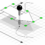
Now that we’ve got an arrow and a plane, how (on Earth) do we get it to look like it is poking through the plane?
Sending to Back or Bringing to Front (Shape > Order menu) doesn’t seem to help us very much:

Because parts of the arrow are in front of the plane, and parts are behind. So we need to operate again. Yup, get your scalpel out, our arrow will require further surgery.
Hopefully you’ve saved a few copies of those fake isometric “1 to 4” lines from earlier. Here I’ve copied one to the position where I guess the arrow hits the plane:
![]()
I’ve also added a vertical line at the right edge of the plane. These two red lines will be used to cut our freshly-union-ed arrow into pieces:
![]()
Once we’ve fragmented, we can delete that extra bit that shows up as a result of where the red lines intersected.
Another tip: to preserve the orange fill in the fragmented shapes, make sure you select the arrow first, then the red lines. It goes like this:
- Press and hold the Shift key
- Click the arrow
- Click a red line
- Click the other red line
- Shape > Operations > Fragment
The resulting shapes will have the line, fill and text attributes of the first-selected shape!
Using Ctrl+Shift+B, we can quickly send the middle bit of the arrow to back, so that it is obscured by the plane:

Make it Really Stand Out
And for further effect, add transparency to the plane, so that the middle of the arrow shows through just a little bit. Transparency can be set under the Format > Fill dialog.

There you have it! A fairly simple-to-create, yet realistic, 3D illustration. All done in Visio, so you don’t have to go out and buy Adobe Illustrator!

Awesome…
Instead of fake/approximate 3d grids, why not use one that is exactly Isometric? VisioCafe.com has true Isometric template pages for exactly this type of drawing. The one called ISO is letter, and ISO-A4 is metric.
http://www.visiocafe.ca/templates.htm
I don’t think he meant that “fake” was a bad thing, it was fecicious. Don’t think there was any requirement for isometric either. I thought the drawing tips were cool!
How can i make Stencils with Visio 2010?
Hi Mike,
That’s a pretty broad question. Does it relate to this post somehow? You might want to try out our discussion forums at http://www.visguy.com/vgforum
Cheers,
Chris
I wanted to do a similar thing with an isometric tube. Is there a way to make a tube shape that when you put longer thinner tubes through it the overlaps are always correct? Resizable and multiple tubes within tubes would be the great.
Hi Jason,
You can draw isometric tubes, then cut them and use transparency similar to the techniques described in this article.
This article + video might be of interest in making the tube sides properly touch the circular openings: http://www.visguy.com/2009/12/10/faking-3d-in-visio/#comments
Making SmartShapes that can have inner- and outer diameters changed would probably also be possible, but quite a bit more difficult!
Legendary! Thanks for that tutorial. I’m just getting into the swing of using Visio for diagramming now, and I’m really enjoying using your site and following these cool tut’s.
I was wondering why the use of perspective points were not used to draw the primary shapes. Two points on or off the drawing page works pretty good.
thanks for your site!
Hi Hugh,
It’s an oblique drawing, so no perspective was needed. For smaller objects, oblique/isometric is easier. Perspective requires too many construction lines and can get out of hand, but it definitely works well with fragment!
Great work guys!
Is it possible to enter a formula to create a helix?
Thanks in advance!
No, no formulas for helices. This might be of interest, though:
http://www.visguy.com/2006/10/19/spiral-shape-maker/
Sorry, posted this request under the wrong post 😀