 Visio is a 2D drawing and diagramming application that doesn’t support 3D modeling functions. But if you like to draw and aren’t afraid of advanced functionality, you can create some decent affects and save the expense/learning curve of other programs.
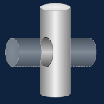
Recently, in the comments for another Visio Guy article, Paul asked how to make a cylinder with a hole through it. While I think he was asking how to draw a 3D disk to create a washer, my mind wandered to something a bit different. A long cylinder like a bolt, with a hole in it–like some fancy fastener you would find while assembling a table from IKEA, and shown in the thumbnail graphic for this article.
Visio’s ‘Boolean’ Operations
To create a graphic like the one shown in this article’s thumbnail, you will need access to the Visio’s “Boolean operations” functions. These allow you cut shapes into pieces and blend them back together again. In this example, we’ll be specifically using the Fragment and Union functions to split shapes at their intersections, and merge selected sliced bit together again.
In Visio 2010 and newer, you need to turn on the Developer tab by right-clicking the ribbon and choosing Customize the Ribbon. Then you’ll find the functions under Developer > Shape Design > Operations.
In Visio 2007 and earlier, you’ll find the Boolean operations under Shape > Operations.
Creating a Cylinder with a Hole
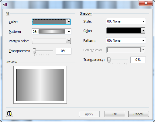
The first thing we need is a shiny cylinder to work with. We can simply draw an elongated rectangle, then give it a reflective look using fill pattern 26. Just draw a rectangle using the rectangle tool, then right-click the shape and choose Format > Fill.
You can see how I’ve chosen a dark gray and a lighter gray to give a (hopefully) tasteful gradient fill to the rectangle.
Now we need to create the effect of a hole through the cylinder. We can do this with two elongated ellipses, one narrower than the other. I’ve given the ellipses a 50% transparent fill, so that we can easily see where they overlap. You can use the arrow keys to nudge selected shapes into place, and use Shift + Arrow to finely nudge a shape just an iota to get the positioning just right:
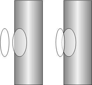
With the ellipses properly positioned, we can cut all three shapes to get our hole. To maintain formatting, we’ll select the cylinder itself first, then hold down the Shift key and select the ellipses afterwards.
When we click on the Fragment function (remeber: Developer > Shape Design > Operations > Fragment)
The more info
resulting pieces will have the formatting of the primary selection (shape we selected first.) It looks a bit funny because of the gradient fill:

To make it clearer in the left figure below, I’ve highlighted the fragmented pieces in red, and removed the gradient:
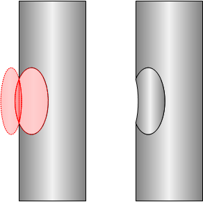
Once you’ve got the pieces, you can delete the bits that are outside the cylinder, as shown on the right above. You can see why we used a thick ellipse and a thin ellipse, and the shape of the hole looks about right. But the formatting is still wrong.
I remedied this by selecting the hole shape, and changing the fill pattern to 29, using the same Fill dialog shown earlier. I also darkened the colors to simulate the effect of less light reaching the innards of the hole.

You may be thinking that the ends of the cylinder look a bit blocky. We can fix that using similar techniques.
Below, I’ve drawn two identical ellipses that serve to give the top and bottom ends some depth.
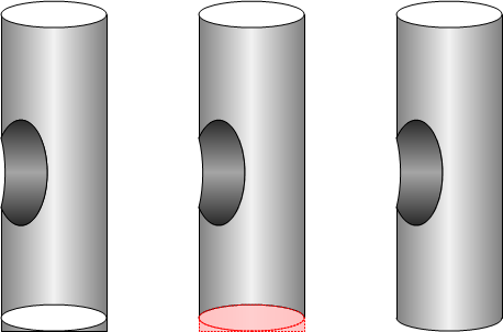
Here are the steps to get the finished product:
- Draw two identical ellipses and position them at the top and bottom of the shiny cylinder (left)
- Select first the cylinder, then the bottom ellipse, and fragment them (middle)
- Delete the extra corner pieces on the bottom.
- Union the remaining two pieces together. Select first the shiny cylinder, then the bottom ellipse, and choose Union from the Boolean operations menu.
- Send the shiny cylinder to back (right-click > Send to Back > Send to Back or right-click > Shape > Send to Back) This brings the top ellipse back to the foreground so we can see it!
For the final dress-up, I gave the cylinder end caps a fill pattern of 40, which emanates from the center, and I made the line color more subtle so that the illustration isn’t too cartoon-ish.
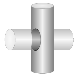
I then created two more cylinders using similar fragment, union and fill-pattern techniques to create the horizontal part. Since there isn’t really a real hole anywhere, the horizontal cylinder needs to be in two parts: one in front, one in back of the vertical cylinder. This allows us to make it look like it is actually passing through the hole! You’ll also note that the horizontal cylinder has a transparent fill so that our fancy hole isn’t obscured.
If you found this article interesting and useful for your projects, be sure to check out these related pieces as well:

very interesting to see how you manipulate the shapes.
thank you for your research and accurate description.
That’s impressive. Can you recommend a book that teaches how to draw objects like that but simpler? I need to make shapes of refrigeration parts such as coils and expansion valves. Is there a term for kind of drawing with Visio? Thanks